Control When Charts Execute by Using Temporal Logic Operators
You can control when Stateflow charts execute by using temporal logic operators. Temporal logic operators track events, count occurrences, and measure elapsed time. You can apply these operators in state actions and transitions to create timing-dependent behaviors, establish delays between states, detect input values at specific times, and filter transient signals.
Use Temporal Logic Operators
You can use event-based operators to track events, or absolute-time operators to track elapsed time. For a list of temporal operators, see Control Chart Execution by Using Temporal Logic.
Event-Based Temporal Logic Operators
Use these operators to track recurring events:
after(n,E): Returns true if eventEoccurs at leastntimes after the state becomes active.at(n,E): Returns true if eventEoccurs exactlyntimes after the state becomes active.before(n,E): Returns true if eventEoccurs fewer thanntimes after the state becomes active.every(n,E): Returns true at everynth occurrence of eventE.temporalCount(E): Returns the number of occurrences of eventE.
This example shows a motor controller that transitions between the
Off, Start, and Run states when
event E occurs. The controller starts in the Off
state with zero motor speed and advances to the Start state when it
detects the start button press. After event E occurs five times, the
controller transitions to the Run state, increases the motor speed to
full, and returns to the Off state when it detects the stop button
press.
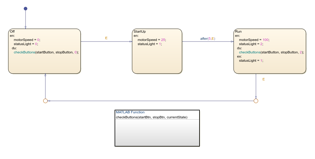
The MATLAB function handles the event broadcasting for the state transitions in the motor controller. The MATLAB function contains this code:
function checkButtons(startBtn, stopBtn, currentState)
if startBtn == true && currentState == 0
    send(E);
elseif stopBtn == true && currentState == 2
    send(E);
end
end
The checkButtons function broadcasts event E
based on button inputs and the current state value. It sends event E
when the start button is pressed and the chart is in the Off state or
when the stop button is pressed and the chart is in the Run
state.
Absolute-Time Temporal Logic Operators
Use these operators to track the time that elapses after a state becomes active:
after(n,sec): Returns true afternseconds of state activation.after(n,msec): Returns true afternmilliseconds.after(n,usec): Returns true afternmicroseconds.temporalCount(sec): Returns the time elapsed, in seconds.elapsed(sec): Same astemporalCount(sec).duration(C,sec): Returns the time elapsed since conditionCbecame true, in seconds.
Implement Time Delays
You can use time delays in control systems to model real-world process lag, filter noisy
signals, and prevent rapid state oscillations. Implement time delays by using temporal logic
operators such as after, at, and
duration. Use these techniques when you need precise timing for state
transitions or want to develop systems that respond only to sustained input signals rather
than transient noise.
To add a time delay to a chart:
Create a chart that includes states that represent different operating modes.
Use absolute-time temporal logic on transitions between states.
Specify the time delay by using
after(n,sec),after(n,msec), orafter(n,usec).
This example shows a TempControl state that manages heating and
cooling operations in a building by using absolute-time temporal logic.
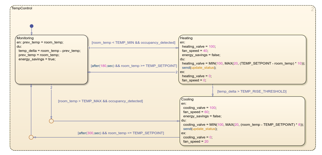
The system monitors room temperature and transitions to the Heating
state when temperature falls below the minimum threshold or the Cooling
state when it exceeds the maximum threshold. The Heating and
Cooling states both implement minimum run times by using absolute-time
temporal logic operaterations after(180,sec) and
after(300,sec). These operations specify timing requirements that are
independent of the step size of the model, which creates consistent HVAC operation
regardless of other simulation parameters.
Detect Elapsed Time
You can detect when input values meet time-based conditions by using temporal logic
operators such as before, after, and
duration. You can also configure charts to transition between states
based on how long conditions remain true. Use these operators to monitor when inputs cross
thresholds inside specific time windows, filter out transient signals, or implement
time-based fault detection logic.
This chart shows how to use the duration operator to track elapsed
time in a motor temperature control system.
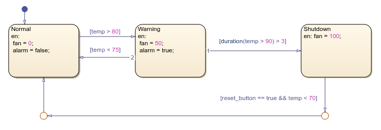
The chart contains the states Normal, Warning, and
Shutdown. The system starts in the Normal state with
the fan off. If the temperature exceeds 80 degrees Celsius, the system transitions to the
Warning state and activates the fan at 50 percent speed. If the
temperature stays above 90 degrees Celsius for more than three continuous seconds, the
system enters the Shutdown state and runs the fan at 100 percent. When
the reset button is pressed and the temperature drops below 70 degrees Celsius, the system
returns to the Normal state.
Debounce Signals
Debouncing is a technique that filters out unwanted transient signals that occur when mechanical switches change state. Without debouncing, a single button press can register as multiple inputs, which can cause erratic behavior like duplicate characters when typing. In control systems, debouncing prevents rapid oscillation between states that could damage equipment or waste energy.
Use operators like duration and after to
implement debouncing.
This chart shows a two-state debouncer that filters noisy input signals into clean
binary outputs. The debouncer uses the duration operator to check that
the input signal remains above or below a threshold for a specified time period before
changing states.
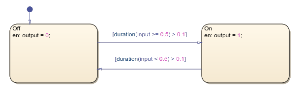
Each state sets a different output value. The output is a stable signal that ignores transient noise.