Design Operating and Failure Mode Control Systems for a Drilling Rig
This example shows how to model the control and failure mode identification systems for a drilling rig. To model the control system, the example uses Stateflow® charts that use Simulink® functions, graphical functions, and history junctions. During simulation, the model uses animations to show the movement of the drill.
Drilling rigs use a powered cable hoist known as a drawworks to raise or lower the top drive and drill string in the wellbore. The drawworks must have operating limitations that ensure the safety of employees and equipment. For example, if the top drive moves too high, the equipment may drop to the ground and endanger workers. If the top drive moves too low, the equipment may become damaged. The top drive must also move at a reasonable speed. Additionally, the drawworks must be able to:
Operate automatically or manually
Operate in normal or limited power modes
Activate an emergency stop switch
Open Model
Open the sfDrawworks model. This model represents the equipment as a plant and controller.
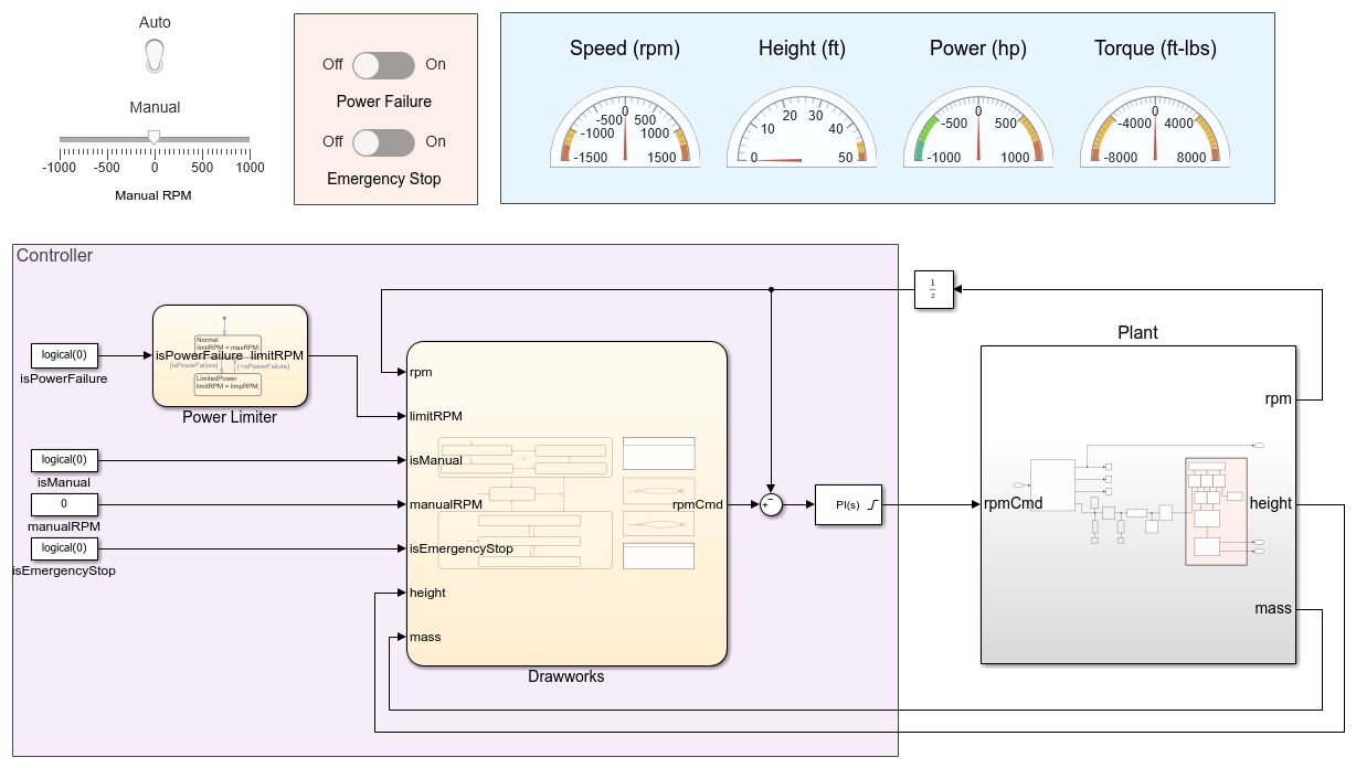
The Controller area contains blocks that coordinate to send a command signal to the plant:
The
Power Limiterchart defines the maximum RPM of the drawworks.The
Drawworkschart sets the desired RPM.The
PID Controllerblock ensures the RPM remains consistent.
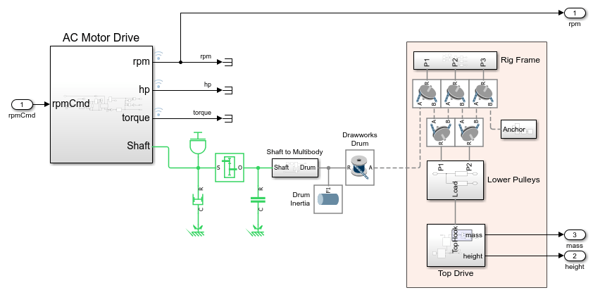
Open the Plant subsystem. This subsystem models the drilling rig. It uses real-world data to represent the movement and operation of the drill.
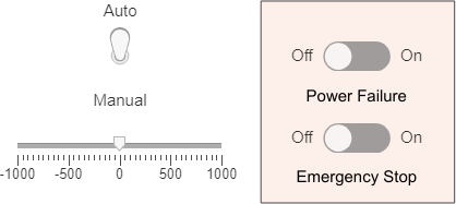
Return to the top-level model. To test different operating modes, use the switches in the upper-left corner of the model. When you flip these switches, the model activates or deactivates different components.
You can use this model to prototype, test, and validate embedded code, and then deploy the embedded code to the equipment.
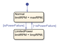
Examine the Power Limiter
To move the drill, the drawworks spools or unspools cable from a cylindrical drum. The Power Limiter chart sets the maximum rotations per minute (RPM) of the drum based on the power mode. The Normal state has a higher maximum RPM than the LimitedPower state.
When the chart is in the LimitedPower state, the maximum RPM is the highest value that does not overtax the power supply.
Examine the Drawworks Controller
The Drawworks chart uses the states Manual, Auto, and Stop to model the control logic of the drawworks.
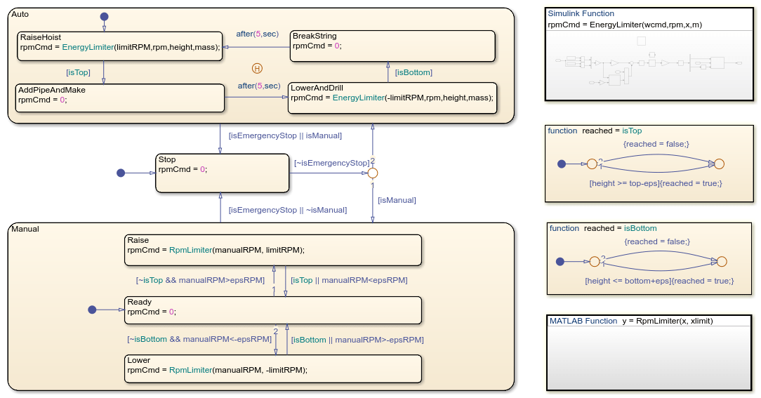
Manual Control
You can use the Manual state to control the upward and downward movement of the drill.
When the chart enters this state, it begins in the child state Ready, which sets the RPM of the drum to 0. Then, the chart transitions between the child states based on the input data manualRPM. The chart transitions to the Raise state when manualRPM is positive, to the Ready state when manualRPM is close to zero, and to the Lower state when manualRPM is negative. The parameter epsRPM defines the threshold at which manualRPM is positive, negative, or neutral.
Before moving from Raise to Lower or from Lower to Raise, the chart must move through the Ready state. This transition forces the drawworks to pause movement before changing direction. Additionally, the chart moves to Ready if the drill reaches the top or bottom of the drill shaft.
In the Raise and Lower states, the MATLAB Function RpmLimiter prevents the RPM of the drawworks from exceeding the maximum allowed RPM. The Power Limiter chart outputs this data to the Drawworks Controller chart.
Automatic Control
The Auto state represents the automatic control mode for the drill. When the chart first enters Auto, it begins in the child state RaiseHoist, which raises the drill. When the drill reaches the top of the rig, the chart transitions to the AddPipeAndMake state, which adds a pipe segment. Then, the chart transitions to the LowerAndDrill state, which lowers the drill, then to the BreakString state, which disconnects the current top segment. Finally, the chart returns to the RaiseHoist state.
In the RaiseHoist and LowerAndDrill states, the Simulink Function EnergyLimiter sets the speed of the drawworks based on the current RPM of the drum, the height and mass of the drill, and the maximum allowed RPM.
When the chart leaves the Auto state, the history junction records the most recent active child state. When the chart returns to the Auto state, it returns to the same child state.
Operational Pause
The Stop state represents a pause in the operation of the drawworks. The chart moves to the Stop state when a user:
Activates the emergency stop, represented by the input
emergencyStop.Moves between the manual and automatic operating modes, represented by
AutoandManual, respectively.
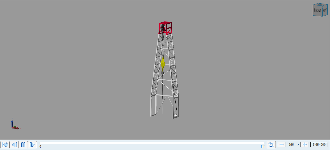
Simulate the Model
Simulate the model. The Multibody Explorer window opens and shows the movement of the drill.
You can observe the operation of the drawworks by using the interface at the top level of the model. The switches change the values of the isPowerFailure, isManual, and isEmergencyStop signals in the top-level model.
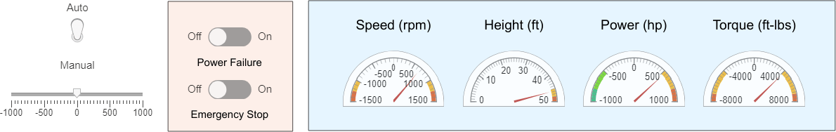
To change between automatic and manual operating modes, click the associated switch. To move the drill in manual mode, drag the slider below the switch.
To activate a power failure or emergency stop, toggle the associated switches.
As the model simulates, the values in the dashboard change. For example, when you manually operate the drill during a power failure, the RPM of the drum never exceeds 500.