Manage Symbols in the Stateflow Editor
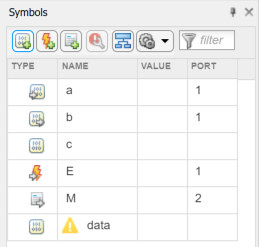
In the Symbols pane, you can view and manage data, events, and messages while working in the Stateflow® Editor. In the Modeling tab, select Symbols Pane.
From the Symbols pane you can:
Add and delete data, events, and messages.
Set the object type and scope.
Change the port number.
Edit the name of an object and update all references to the object name in the chart.
Undo and redo changes in type, name, and port number.
Detect unused objects.
Detect and fix unresolved objects.
Trace between objects in the window and where the objects are used in the chart.
View and edit object properties in the Property Inspector.
The rows in the Symbols pane display object hierarchy. Expand an object in the window to see data, events, and messages parented by that object. By default, all the nongraphical objects in a chart are listed in the window. To view only the objects that are used at the current level of hierarchy and below, select the icon. To search for specific symbols, type in the Filter search box .
Add and Modify Data, Events, and Messages
To add a nongraphical object to a Stateflow block, in the Symbols pane:
Select one of these icons.
Icon Description Add data Add event Add message In the row for the new object, under TYPE, choose the object type.
Edit the name of the object.
For input and output objects, under PORT, choose a port number.
To view the object in the Property Inspector, right-click the object and select
Inspect
.In the Property Inspector, modify the object properties.
After you add objects through the Symbols pane, the objects appear as unused until you reference them in your Stateflow design.
In the Symbols pane, you can modify the name, type, and port number of Stateflow objects. Edit the name of objects in the NAME field. When you rename an object, select Shift+Enter to rename all references to the object throughout the chart. To change the type or port number of an object, click the corresponding field and select from the available options. To delete an object, right-click the object and select Delete.
Detect Unused Data in the Symbols Pane
The Symbols pane indicates unused data, messages, functions, and events with a yellow warning icon . You can resolve undefined symbols by using the Symbols pane or the Symbol Wizard.
The Symbols pane does not detect inputs and outputs of MATLAB® functions or parameters in atomic subcharts.
To delete unused objects, right-click the object in the Symbols pane
and select Delete. By removing objects that have no
effect on simulation, you can reduce the size of your model. In this chart, after
you add data
, it first appears as unused. After you reference
data
in the chart, the warning sign disappears.
Resolve Symbols Through the Symbols Pane
Symbols that appear in your chart but that you have not added as data, events, or messages are undefined or unresolved. As you edit your chart, Stateflow detects undefined symbols and marks them in the Symbols pane with a red error icon .
For each undefined symbol, the Symbols pane displays the class and scope inferred from the usage in the chart. You can resolve undefined symbols individually or collectively.
To define a symbol with the inferred class and scope, click the error icon and select Fix.
To define a symbol with a different class or scope, select another combination of class and scope from the TYPE drop-down list.
To resolve all of the undefined symbols with their inferred classes and scopes, click the Resolve undefined symbols button .
Resolve Symbols Through the Symbol Wizard
If your chart contains any undefined symbols when you update the chart, update the model, or simulate the model, the Symbol Wizard opens and lists the undefined symbols. For each undefined symbol, the Class and Scope columns display the class and scope inferred from the usage in the chart. You can accept, modify, or reject each symbol definition that the Symbol Wizard suggests.
To accept a definition with the inferred class and scope, select the check box in front of the symbol.
To modify a definition, select a different class or scope from the Class or Scope drop-down lists.
To reject a definition, clear the check box in front of the symbol.
After you edit the symbol definitions, add the symbols to the Stateflow hierarchy by clicking OK.
Detect Symbol Definitions in Custom Code
Detection of symbols defined in custom code depends on the model configuration parameter Import custom code.
If you select Import custom code, the Stateflow parser tries to find unresolved chart symbols in the custom code. If the custom code does not define these symbols, they appear in the Symbol Wizard.
If you do not select Import custom code, the Stateflow parser considers unresolved data symbols in the chart as defined in the custom code. If the custom code does not define these symbols, simulating and generating code from the model results in an error.
The Import custom code option is not available for charts that use MATLAB as the action language. For more information, see Import custom code (Simulink).
Trace Data, Events, and Messages
Stateflow provides traceability between the chart and nongraphical symbols. When you select a symbol in the Symbols pane, Stateflow highlights sections of the chart that access that symbol. When you select an object in your chart, Stateflow highlights the symbols that the object uses.
To control when the objects and symbols are highlighted, select the preference button . A drop-down menu appears.
For Stateflow to highlight symbols in the Symbols pane that an object uses, select Highlight used symbols. If you want Stateflow to highlight objects in the chart that use an symbol, select Highlight uses on diagram. With Highlight uses on diagram, you can choose to highlight:
All uses of the symbol in your chart.
Objects from where the symbol is read.
Objects to where the symbol is written.
Note
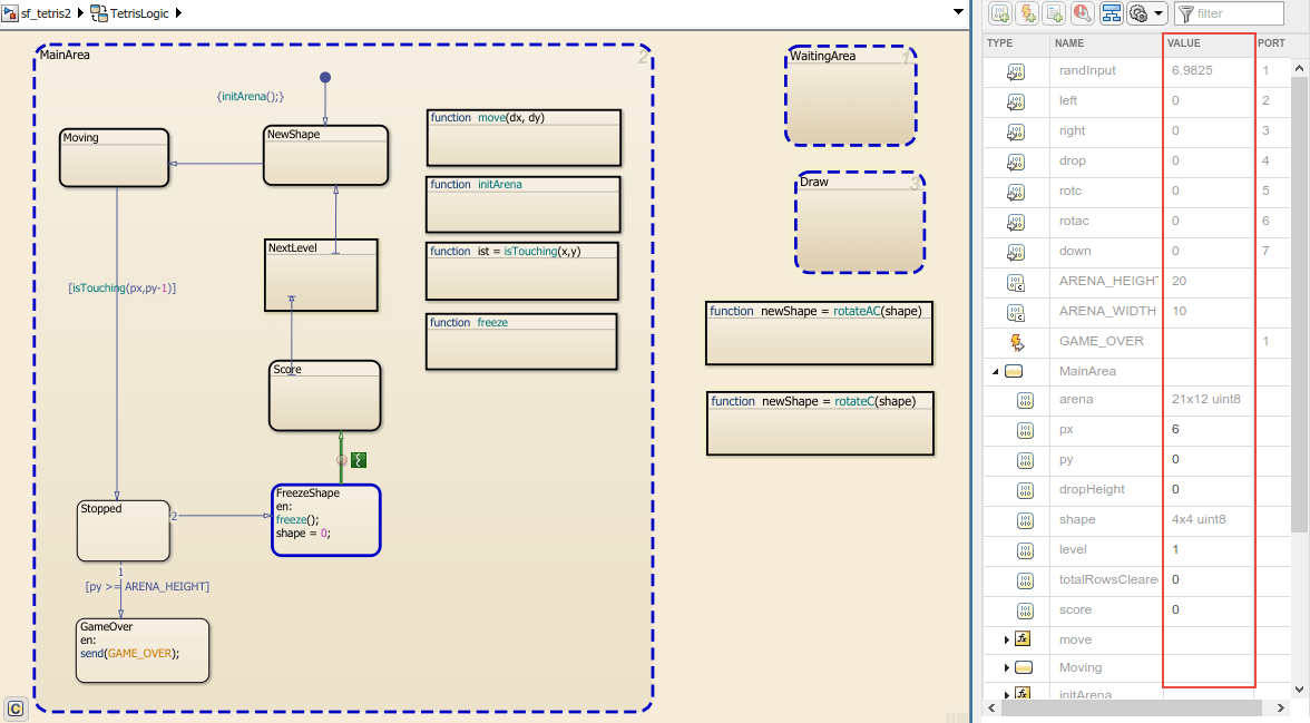
Use the Update value column during simulation option to allow the values shown in the symbol pane to update during simulation.
For example, open the model sf_tetris2
.
openExample("sf_tetris2")
Double-click the chart TetrisLogic
. In the Symbols
pane, when you select constant ARENA_HEIGHT
, the states and
functions that use ARENA_HEIGHT
are highlighted.
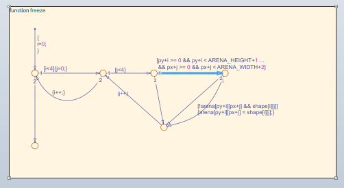
To see the uses of the constant ARENA_HEIGHT
, open the function
freeze
.
You can also select a graphical object such as a state, transition, or function in the
chart and view the symbols that the object uses. For example, in the chart
TetrisLogic
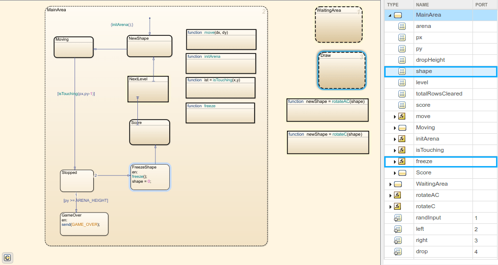
, expand the symbol MainArea
in
the Symbols pane. If you select the state
FreezeShape
in the chart, then the local data
shape
and the function freeze()
are
highlighted in the Symbols pane. This highlighting indicates
that those objects are used inside the state FreezeShape
.
When in debugging mode, the values of each data are displayed in the VALUE column of the Symbols pane. Stateflow updates the values periodically when the simulation is running. The value column highlights changes to data values as the changes occur. When the debugger is stopped at a breakpoint, you can update the initial value or change the value of a symbols in either the command prompt or the Symbols pane.
Data or Message | Update Initial Value | Update During Debugging |
---|---|---|
Input | No | No |
Output | Yes | Yes |
Parameter | No | No |
Constant | Yes | No |
Data Store Memory | No | Yes |
Local | Yes | Yes |
For bus elements, you can change the value of a symbols in either the command prompt or the Symbols pane.
Bus Element | Update Initial Value | Update During Debugging |
---|---|---|
Input | No | No |
Output | No | Yes |
Parameter | No | No |
Constant | No | No |
Data Store Memory | No | Yes |
Local | No | Yes |
In the Symbols pane multidimensional arrays appear as the data type and size of the array. If the array does not exceed more than 100 elements, hover over the symbol to view the elements. For arrays that contain more than 100 elements, view the elements by using the command prompt.
When simulation is paused, hover over messages in the canvas to view payloads in the queue. This is similar to the hover functionality on the canvas. For other non-scalar objects, the size and data type appear. To see these values, use the Watch window. See Inspect and Modify Data and Messages While Debugging and Track Data in the Watch List.
Symbols Pane Limitations
You cannot add data, events, or messages the Symbols pane if they are parented by a state or function. To add these types of objects, use the Model Explorer.
When you modify the code in a MATLAB function, the changes are not updated in the Symbols pane until after you save the MATLAB function.
You cannot undo or redo changes to input and output for MATLAB functions.
You cannot recover deleted data, events, or messages from a state transition table.
You cannot undo scope changes to data parented by graphical functions, MATLAB functions, and truth tables.
You cannot undo renaming an object for truth tables.
When you delete data for objects contained in a Simulink based state, the object remains in your Simulink based state and the data symbol is shown as undefined in the Symbols pane.