BNO055 IMU Sensor
Measure acceleration, angular rate, and magnetic field, and calculate Euler angles, quaternion, linear acceleration, and gravity vector along the axes of BNO055 sensor
Since R2026a
Libraries:
STM32 Microcontroller Blockset /
Sensors /
IMU Sensors
STM32 Microcontroller Blockset /
(Legacy) STM32 MBED Based Boards /
MBED Based Sensors
Description
The BNO055 IMU Sensor block reads data from the BNO055 IMU sensor connected to the hardware. The block operates in two modes: Non-Fusion and Fusion.
The block outputs acceleration, angular rate, and magnetic field strength along the
sensor axes in both Non-Fusion and Fusion modes. In Fusion mode, the block also outputs the
sensor's orientation as Euler angles or quaternions, as well as linear acceleration,
gravity vectors, and calibration status. In Non-Fusion mode, the block outputs raw values;
in Fusion mode, it outputs calibrated values. The block outputs all the values except for
quaternion and calibration status as a 3-by-1 array of
double data type. The quaternion is a 4-by-1
array of double data type, and the calibration status is a
4-by-1 array of int8 data type.
If you simulate a model that contains the BNO055 IMU Sensor block without connecting the hardware, the block outputs zeros. For more information, see Block Produces Zeros or Does Nothing in Simulation.
Examples
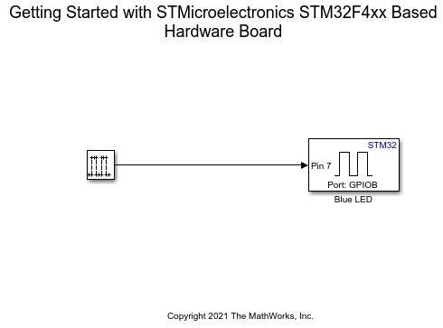
Get Started with STMicroelectronics STM32 Processor Based Boards
Run a Simulink model on STM32 processor.
Ports
Output
Acceleration in m/s2 along the x-, y-, and z- axes of the sensor, output as an 3-by-1 vector. In fusion mode, the elements of the vector represent calibrated values, whereas in non-fusion mode, the elements represent raw values. The acceleration is measured also includes acceleration due to gravity.
Dependencies
To enable this port, select the Acceleration (m/s2) parameter.
Data Types: double
Angle of rotation per second about the x-, y-, and z- axes of the sensor, output as an 3-by-1. In fusion mode, the elements of the vector represent calibrated values, whereas in non-fusion mode, the elements represent raw values. The angular rate is measured in dps.
Dependencies
To enable this port, select the Angular rate (dps) parameter.
Data Types: double
Strength of the magnetic field along the x-, y-, and z- axes of the sensor, output as a 3-by-1 vector. In Fusion mode, the elements of the vector represent calibrated values, whereas in Non-Fusion mode, the elements represent raw values. The magnetic strength is measured in μT.
Dependencies
The Magnetic field port is available only when you select the Magnetic field (μT) parameter.
Data Types: double
Orientation along the axes of the sensor, output as a 3-by-1 vector in the Azimuth-Pitch-Roll notation (z-y-x sequence).
| Angular Quantity | Range in Degrees |
|---|---|
| Azimuth | [0, 360] |
| Pitch | [−180, 180] |
| Roll | [−90, 90] |
Dependencies
The Euler Angles port is available only when you set
the Operation mode to Fusion
and select the Euler angles (degrees) parameter.
Data Types: double
Orientation along the w-, x-, y-, and z- axes of the sensor, output as a 4-by-1 vector. The orientation is measured in quaternion.
Dependencies
The Quaternion port is available only when you set
the Operation mode to Fusion
and select the Quaternion (quaternion)
parameter.
Data Types: double
Linear acceleration along the x-, y-, and z- axes of the sensor, output as a 3-by-1 vector. The acceleration is measured in m/s2 and does not include acceleration due to gravity.
Dependencies
The Linear acceleration port is available only when
you set the Operation mode to
Fusion and select the Linear
acceleration (m/s^2) parameter.
Data Types: double
Acceleration due to gravity along the x-, y-, and z- axes of the sensor, output as a 3-by-1 vector. The acceleration due to gravity is measured in m/s2.
Dependencies
The Gravity Vector port is available only when you
set the Operation mode to
Fusion and select the Gravity vector
(m/s^2) parameter.
Data Types: double
Calibration status of the overall system and the sensors (gyroscope, accelerometer, and magnetometer) located inside the BNO055 sensor, output as a 3-by-1 vector.
This table shows what each element values in the vector indicate about the sensor calibration status.
| Value | Calibration Status |
|---|---|
0
| Uncalibrated |
1 and 2
| Partially calibrated |
3
| Fully calibrated |
A partially calibrated sensor with a calibration status of
2 provides more accurate readings than the sensor with a
calibration status of 1.
Note
If the Calibration status port outputs an array with
all the elements having a value of -1, ensure that the
sensor is properly connected to the hardware and the value of the
I2C address parameter is correct.
Dependencies
The Calibration status port is available only when
you set the Operation mode to
Fusion and select the
Status parameter.
Data Types: int8
Parameters
Specify the I2C module on the STM32 processor to communicate with sensor peripherals.
Programmatic Use
Block Parameter:
I2cModule |
Select the I2C address of the sensor from which the block read values.
Programmatic Use
Block Parameter:
I2cAddress |
Fusion— When you set Operation mode toFusion, the sensor operates in 9 degrees of freedom (NDOF) mode. The block outputs calibrated values from the sensor.This table lists the block output, measurement unit, dimension, and the axes of the sensor along which each of these outputs are measured.
Output Unit Dimension Axes Acceleration Meter per second squared (m/s2) 3-by-1 x, y, and z Angular rate Meter per second squared (m/s2) 3-by-1 x, y, and z Magnetic field microtesla (μT) 3-by-1 x, y, and z Euler angles degrees per second (dps) 3-by-1 x, y, and z Quaternions Quaternion units 4-by-1 w, x, y, and z Linear acceleration Meter per second squared (m/s2) 3-by-1 x, y, and z Gravity vector Meter per second squared (m/s2) 3-by-1 x, y, and z Note
In Fusion mode, an internal fusion algorithm configures the range and bandwidth of the sensor with some values. These values cannot be modified.
Non-Fusion— When you set Operation mode toNon-Fusion, the sensor operates in Accelerometer Magnetometer Gyroscope (AMG) mode. The block outputs raw values from the sensor.This table lists the block output, measurement unit, dimension, and the axes of the sensor along which each of these outputs are measured in Non-Fusion mode.
Output Unit Dimension Axes Acceleration Meter per second squared (m/s2) 3-by-1 x, y, and z Angular rate Meter per second squared (m/s2) 3-by-1 x, y, and z Magnetic field microtesla (μT) 3-by-1 x, y, and z
Programmatic Use
Block Parameter:
OperationMode |
Specify how often the block read values from the sensor, in seconds. When you
specify this parameter as -1, Simulink® determines the best sample time for the block based on the block
context within the model. The output sample time is the product of
Sample time that you specify.
Programmatic Use
Block Parameter:
SampleTime |
Select Outputs
When you select the Acceleration (m/s^2) parameter, the Acceleration port becomes available. For more information on the Acceleration port, see Acceleration.
Programmatic Use
Block Parameter:
Acceleration |
When you select the Angular rate (dps) parameter, the Angular Rate port becomes available. For more information on the Angular Rate port, see Angular rate.
Programmatic Use
Block Parameter:
AngularRate |
When you select the Magnetic field (μT) parameter, the Magnetic Field port becomes available. For more information on the Magnetic Field port, see Magnetic field.
Programmatic Use
Block Parameter:
MagneticField |
Data Types: double
When you select the Euler angles (degrees) parameter, the Euler Angles port becomes available. For more information on the Euler Angles port, see Euler Angles.
Programmatic Use
Block Parameter:
EulerAngles |
Dependencies
The Euler angles (degrees) parameter is available
only when you set the Operation mode to
Fusion.
When you select the Quaternion (quaternion) parameter, the Quaternion port becomes available. For more information on the Quaternion port, see Quaternion.
Programmatic Use
Block Parameter:
Quaternion |
Dependencies
The Quaternion (quaternion) parameter is available
only when you set the Operation mode to
Fusion
Data Types: double
When you select the Linear acceleration (m/s^2) parameter, the Linear Acceleration port becomes available. For more information on the Linear Acceleration port, see Linear acceleration.
Programmatic Use
Block Parameter:
LinearAcceleration |
Dependencies
The Linear acceleration (m/s^2) parameter is
available only when you set the Operation mode to
Fusion.
When you select the Gravity vector (m/s^2) parameter, the Gravity Vector port becomes available. For more information on the Gravity Vector port, see Gravity Vector.
Programmatic Use
Block Parameter:
GravityVector |
Dependencies
The Gravity vector (m/s^2) parameter is available
only when you set the Operation mode to
Fusion.
Select this parameter to display the status of read operation.
When you select the Status parameter, the Calibration Status port becomes available. For more information on the Calibration Status port, see Calibration status.
Programmatic Use
Block Parameter:
Status |
Select this parameter to set Timestamp as one of the output ports.
Programmatic Use
Block Parameter:
Timestamp |
Advanced Sensor Settings (optional)
Specify the deviation in the acceleration that the accelerometer can measure. The smaller the accelerometer range is, the more sensitive the readings from the accelerometer are. A small range provides more detailed data, resulting in a more precise reading from the accelerometer.
Programmatic Use
Block Parameter:
AccelerometerRange |
Dependencies
The Accelerometer range parameter is available only
when you set the Operation mode to
Non-Fusion.
Specify the frequency at which the accelerometer measures acceleration.
Programmatic Use
Block Parameter:
AccelerometerBandwidth |
Dependencies
The Accelerometer bandwidth parameter is available
only when you set the Operation mode to
Non-Fusion.
Specify the maximum angular velocity that the gyroscope can measure per second.
Programmatic Use
Block Parameter:
GyroscopeRange |
Dependencies
The Gyroscope range parameter is available only when
you set the Operation mode to
Non-Fusion.
Specify the frequency at which the gyroscope measures angular velocity.
Programmatic Use
Block Parameter:
GyroscopeBandwidth |
Dependencies
The Gyroscope bandwidth parameter is available only
when you set the Operation mode to
Non-Fusion.
Specify the range of the magnetic field that the magnetometer can read.
Programmatic Use
Block Parameter:
MagnetometerOutputDataRange |
Dependencies
The Magnetometer output data range parameter is
available only when you set the Operation mode to
Fusion
Data Types: double
Extended Capabilities
C/C++ Code Generation
Generate C and C++ code using Simulink® Coder™.
Version History
Introduced in R2026a
MATLAB Command
You clicked a link that corresponds to this MATLAB command:
Run the command by entering it in the MATLAB Command Window. Web browsers do not support MATLAB commands.
选择网站
选择网站以获取翻译的可用内容,以及查看当地活动和优惠。根据您的位置,我们建议您选择:。
您也可以从以下列表中选择网站:
如何获得最佳网站性能
选择中国网站(中文或英文)以获得最佳网站性能。其他 MathWorks 国家/地区网站并未针对您所在位置的访问进行优化。
美洲
- América Latina (Español)
- Canada (English)
- United States (English)
欧洲
- Belgium (English)
- Denmark (English)
- Deutschland (Deutsch)
- España (Español)
- Finland (English)
- France (Français)
- Ireland (English)
- Italia (Italiano)
- Luxembourg (English)
- Netherlands (English)
- Norway (English)
- Österreich (Deutsch)
- Portugal (English)
- Sweden (English)
- Switzerland
- United Kingdom (English)