Estimate PMSM Parameters Using STM32 Processor
This example determines the parameters of a permanent magnet synchronous motor (PMSM) using the recommended STM32xx based board. The tool determines these parameters:
Phase resistance,
 (Ohm)
(Ohm)
dandqaxis inductances, and
and  (Henry)
Back-EMF constant,
 (Vpk_LL/krpm, where Vpk_LL is the peak voltage line-to-line measurement)
Motor inertia,
 (Kg.m^2)
Friction constant,
 (N.m.s)
The example accepts the minimum required inputs, runs tests on the target hardware, and displays the estimated parameters.
NOTE: This example does not support simulation. Use one of the supported hardware configurations to run this example.
Prerequisites
The parameter estimation tool needs the motor position as detected by either a quadrature encoder, a Hall sensor, or a sensorless flux observer. In this example, the speed and motor position are measured using a sensorless flux observer. Ensure that the PMSM is in no-load condition.
Complete the following tutorials:
Required Hardware
PMSM DC power supply as per the motor rating
Hardware Connection
Jumper Connection
Configure the following connections on X-NUCLEO-IHM07M1 board to perform FOC to the control BLY172S-24V-4000 motor.
Prepare and Configure Workspace
Prepare the model and MATLAB workspace so parameter estimation runs correctly on the selected STM32 Nucleo board and inverter combination. This setup aligns the Simulink model, STM32CubeMX project configuration, and motor parameters with the target hardware to ensure correct code generation, deployment, and execution.
1. Open the model Mcb_stm32_param_est_target.slx.
2. Select the inverter board from the model.
3. Open the Modeling tab and press CTRL+E to open the Configuration Parameters dialog box. Go to Hardware Implementation > Hardware board > Target hardware resources > Build options and specify the path to a valid STM32CubeMX .ioc file that matches the selected microcontroller (G431 or G474).
The .ioc file defines pin assignments, clock configuration, and peripheral initialization used during code generation. Using the correct file ensures that the generated code matches the physical hardware connections.
4. Click Apply, then click OK to save the hardware configuration. The example provides validated .ioc files for each supported board and inverter combination:
Nucleo G431 + IHM07M1
Nucleo G474 + IHM07M1
Nucleo G431 + IHM16M1
Nucleo G474 + IHM16M1
Select the file that corresponds exactly to your hardware to avoid deployment or runtime issues.
5. Open the script mcb_stm32_param_est_InitFunc.m and update parameters to match the connected motor and inverter.
The following parameters are required by the parameter estimation algorithm and must reflect the physical motor characteristics:
Input DC Voltage - DC supply voltage applied to the inverter, in volts
Nominal Current - Rated motor current, in amperes
Nominal Speed - Rated motor speed, in revolutions per minute
Pole Pairs - Number of motor pole pairs
Nominal Voltage - Rated motor voltage, in volts
Do not modify the Position offset and Total QEP slits parameters, as they are not used in this example.
6. Optionally adjust control algorithm parameters to suit your application. The default values are validated using a BLY172S motor and provide a known-good reference for motors with similar electrical characteristics.
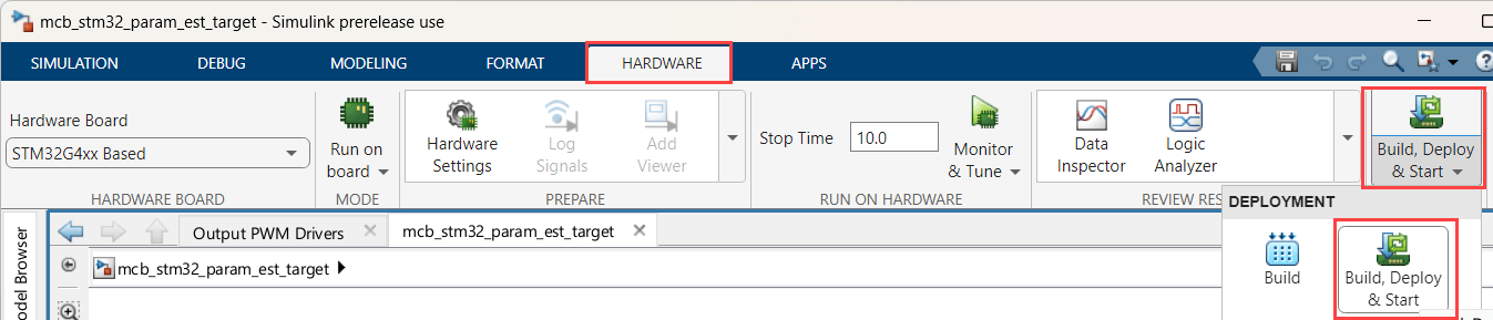
Deploy Model to Target Hardware
Click Build, Deploy and Start. This action generates the executable, programs it into flash memory, and starts execution on the target hardware.
The target model executes real-time control on the hardware, while the host model configures, triggers, and monitors each estimation sequence. This separation lets you adjust estimation settings, start or stop individual estimation runs, and observe results without rebuilding or redeploying the executable.
Configure Estimation Parameters in Host Model
Before running estimation tests, configure the estimation settings that define which parameters are estimated and how each test is executed.
1. Open the host model mcb_stm32_param_est_host.slx and configure the PMSM Parameter Estimation Configuration block by double-clicking it in the host model.
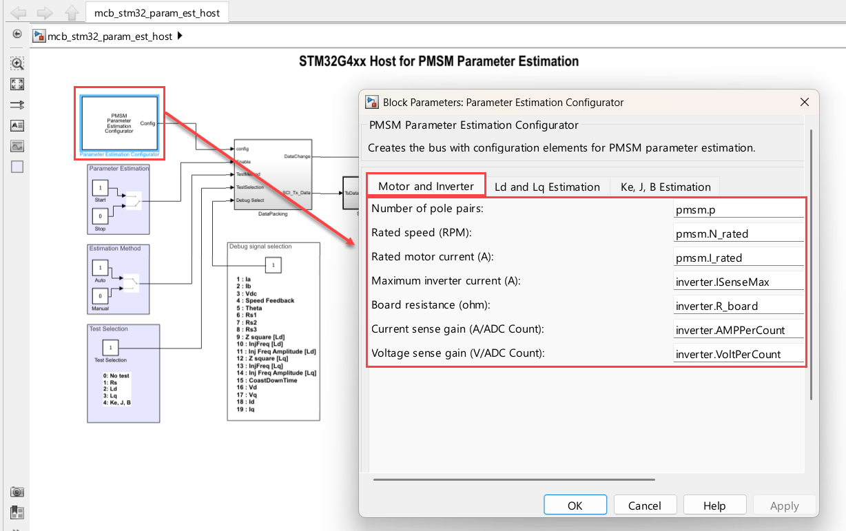
This block defines test sequencing, excitation profiles, and timing used during estimation.
2. Review and update parameters in the Ld and Lq Estimation and Ke, J, B Estimation tabs to match your application requirements.
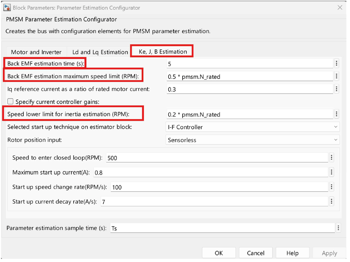
These settings control current injection levels, speed limits, and test durations, which directly affect estimation accuracy and hardware stress. For more information, see PMSM Parameter Estimation Configurator (Motor Control Blockset).
Run Host Model and Execute Estimation Tests
Use the host model to start, monitor, and sequence individual estimation tests while the algorithm runs on the target hardware.
1. Open the host model Mcb_stm32_param_est_host.slx.
2. Before starting the simulation, confirm the initial test conditions:
Set the Parameter estimation switch to STOP.
Set the Estimation Method switch to Manual.
Set the Test Selection constant to 1 to select rotor resistance (Rs) estimation.
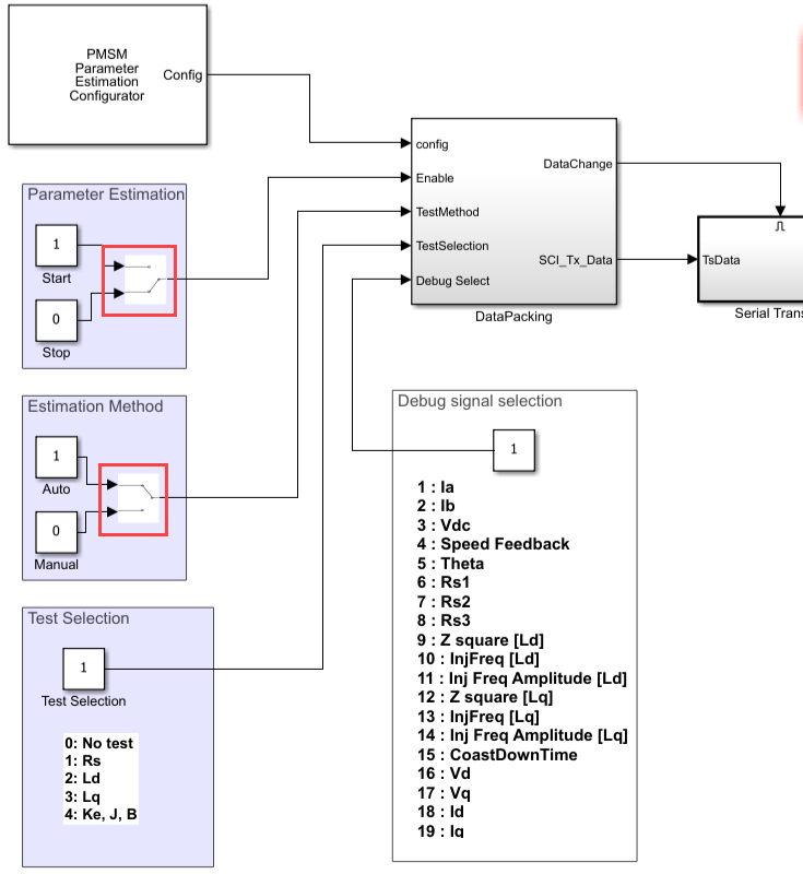
These settings ensure that the system starts in a safe, idle state and that tests are explicitly triggered by the user.
3. To start the host-side control logic, click Run.
You can adjust constants and switch states while the simulation is running to control test flow.
4. To monitor armature current during testing, set the Debug Signal Selection constant to 1. This selection routes phase current (Ia) to the scope, which helps verify expected excitation patterns and detect abnormal behavior.
Execute Individual Estimation Tests
Run each test by selecting the test number and enabling the Parameter estimation switch. The motor behavior during each test provides visual confirmation that the algorithm is operating correctly.
Test 1: Rotor Resistance (Rs) Estimation
Set Test Selection to 1.
Turn Parameter estimation to ON.
Expected behavior:
Armature current ramps linearly to the rated value and returns to zero.
Positive and negative current ramps repeat during the test.
After completion (approximately 30 seconds), current remains at zero and the estimated resistance value appears in the display block.
Turn the Parameter estimation switch OFF after the test completes.
Test 2: Quadrature-Axis Inductance (Lq) Estimation
Set Test Selection to 2.
Turn Parameter estimation to ON.
Expected behavior:
The motor does not rotate.
A brief screeching sound may occur, which is expected.
After a few seconds, turn the Parameter estimation switch OFF.
Test 3: Direct-Axis Inductance (Ld) Estimation
Set Test Selection to 3.
Turn Parameter estimation to ON.
Expected behavior:
The motor remains stationary and may emit a short screeching sound.
Current returns to zero when the test completes.
Turn the switch OFF after completion.
Test 4: Mechanical Parameters and Back EMF Estimation
Set Test Selection to 4.
Turn Parameter estimation to ON.
Expected behavior:
The motor initially rotates in open loop with higher current.
Speed ramps up to the configured maximum back-EMF estimation speed.
Control transitions to closed loop and maintains speed for the configured estimation time.
Duty ratio is set to zero, current drops to zero, and the motor decelerates.
When speed falls below the inertia estimation lower limit, the test completes.
Wait for the motor to stop completely, then turn the Parameter estimation switch OFF.
Review Results
After all tests complete, stop the simulation. The estimated motor parameters are displayed in the model and are also stored in the MATLAB workspace, where you can reuse them for control design, validation, or further tuning.