Motion Planning and RigidBodyTree Simulation of UR5e for Bin Picking Using manipulatorRRT Algorithm
This example shows the motion planning algorithm design workflow for a real-world cobot bin picking application. The rigid body tree considered in this example is for Universal Robots URe5 cobot with the added end-effector along with the suction gripper (Robotiq Vacuum Gripper - EPick).
For a real-world industrial based application, it is important to generate and execute cobot trajectories that avoid the collision with the surrounding environment (that is, design a motion planner that satisfies the collision-free trajectory requirement). This example uses manipulatorRRT algorithm that generates a collision-free path from the starting position to destination, and also uses the contopptraj algorithm to compute the fastest possible way to traverse the path while still stopping at each waypoint.
To know more about how to use manipulatorRRT algorithm for motion planning, refer to this example.
Toolbox dependency
This example uses:
MATLAB®
Robotics System Toolbox™
Optimization Toolbox™
Create Environment with UR5e, Bin, and Parts
Load Universal Robots UR5e Robot as a RigidBodyTree model
Load rigid body tree model for Universal Robot UR5e robot manipulator using importrobot.
ur5eRBT = loadrobot('universalUR5e','DataFormat','row');
Attach Robotiq Vacuum Gripper Body at the Robot End-Effector Body
The function exampleHelperAddGripper is used to attach the additional end-effector body (Robotiq Vacuum Gripper - EPick) as a collision object for precise motion planning.
ur5e = exampleHelperAddGripper(ur5eRBT);
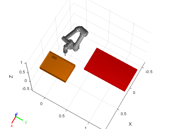
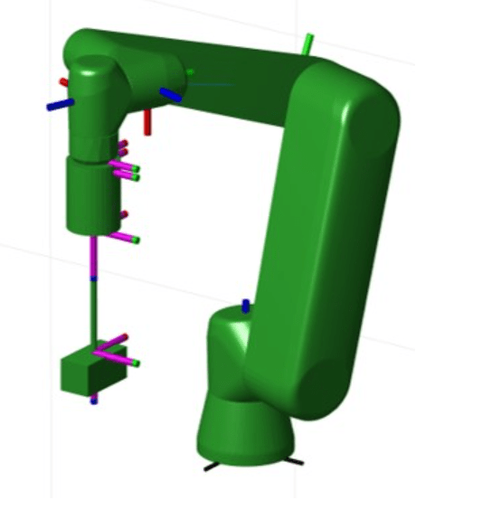
Show Robot RigidBodyTree Model at Home Position
Home position is the initial position of the robot from where we start a pick-and-place cycle. It is also possible to keep the home position same as the retract position, if it is allowed in the environment.
These are the guidelines to select home position of the robot.
Select home position as near to the center of the bin as possible, at some height.
Ensure that the home position is feasible enough for generating a safe trajectory in the collision environment.
If possible, try to select home position same as retract position (Retract position will be discussed in the further section).
% Home Position
homePosition = deg2rad([-15 -126 113 -80 -91 76]);

% Set home position of each joint
ur5e.Bodies{1, 3}.Joint.HomePosition = homePosition(1);
ur5e.Bodies{1, 4}.Joint.HomePosition = homePosition(2);
ur5e.Bodies{1, 5}.Joint.HomePosition = homePosition(3);
ur5e.Bodies{1, 6}.Joint.HomePosition = homePosition(4);
ur5e.Bodies{1, 7}.Joint.HomePosition = homePosition(5);
ur5e.Bodies{1, 8}.Joint.HomePosition = homePosition(6);

% Show robot at home position
f1 = figure;
show(ur5e,homePosition,'Frames','on','PreservePlot',false,'Collisions','off','Visuals','on');
hold on

Bin and Part Dimensions
Define bin and part dimensions. This data will be used to create a collision environment for the motion planner.
Note: All dimensions are in meters.
% bin dimension
binLength = 0.38; % Along X axis
binWidth = 0.57; % Along Y axis
binHeight = 0.11;
binCenterPosition = [0.48 0 -0.09+0.11/2];
binRotation = 0;

% part dimension
partheight = 0.0508;
partWidth = 0.0508;
Plot Bin Along with Robot RigidBodyTree Model
env = exampleHelperPlotBin(binLength, binWidth, binHeight, binCenterPosition, binRotation);
hold on
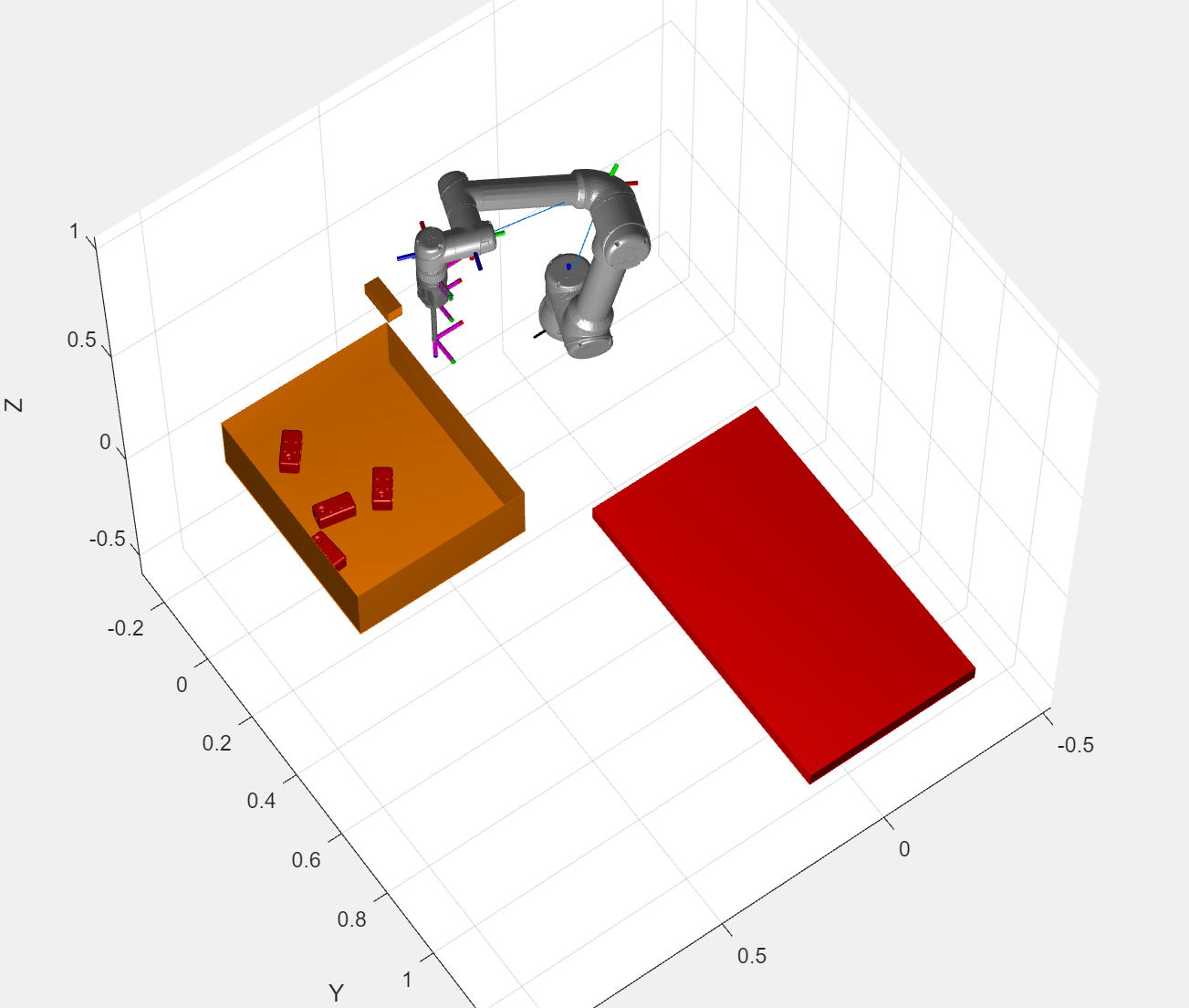
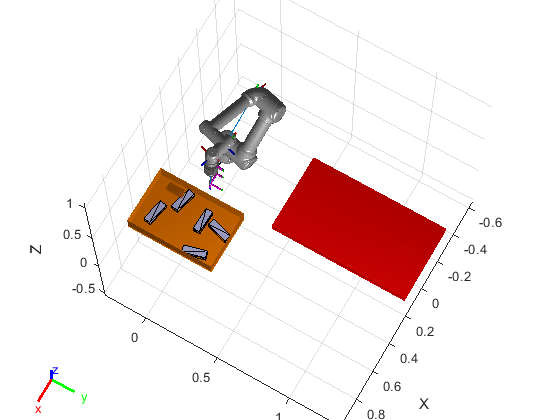
Generate Part's Ground Truth and Plot in the Semi-Structured Environment
This example provides exampleHelperGenerateGT function to generate ground truth for the objects. Another function, exampleHelperPlotParts is used to visualize the parts in the bin in the semi-structured robot environment.
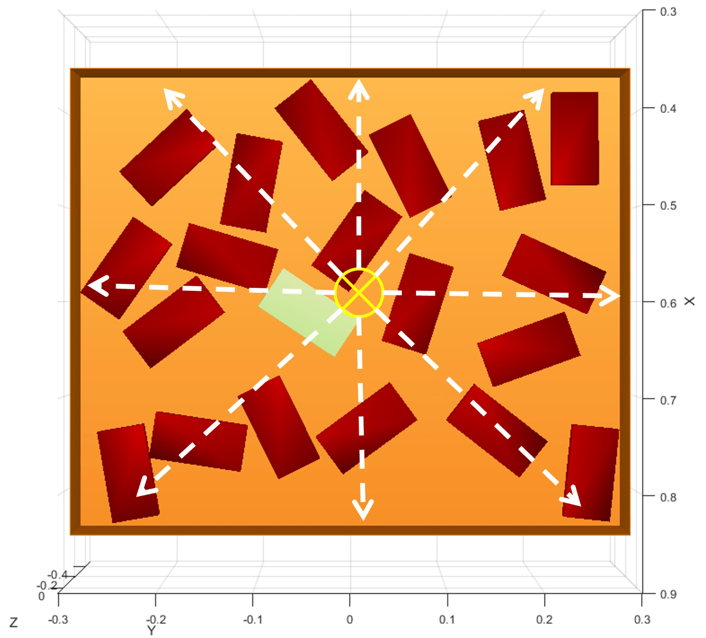
Algorithm to Spawn Parts
The algorithm randomizes the center location of parts in the bin, the rotation of parts with respect to the central axis, and the face on which the parts are lying. After spawning the part, it also checks for the collision with the wall or existing parts and accepts or rejects the newly spawned part accordingly.
Location of Center
The location of the center of the part is generated by randomized algorithm and it lies between the red boundary. The location of the part's center point must be in such a way that it does not collide with the bin wall or the neighbor parts.
Rotation
The rotation of the part is randomized between 0 to 360 degrees. Because the part has a distinct feature on one side, 0 and 180 degrees are not the same configurations.
Collision with Bin Walls and Existing Parts
Collision of each newly spawned part with the bin walls and existing parts in the environment is validated if the part's center is within a specified radius from the boundary or center of the other part. Each part is represented with a collision box.
The part ground truth is defined as the 1x4 array: [centerX, centerY, centerZ, rotationZ]
% Number of parts
numberOfParts = 5;

% Generate part ground truth using randomization approach
[partGT,env] = exampleHelperGenerateGT(binLength, binWidth, binHeight, binCenterPosition, binRotation,numberOfParts,env);

% Plot Parts
exampleHelperPlotParts(binLength, binWidth, binHeight, binCenterPosition, binRotation, partGT);

% Adjust the camera and axis limits
axis auto;
view([120 70]);
drawnow;

% Reset the seed
rng shuffle
Motion Planning
The algorithm used in the upcoming sections uses these flags that you can set to true or false.
showAnimation- if set totrue, MATLAB shows the animation of the robot traversing the path to pick and place the parts.showAnimationTraj- if set totrue, MATLAB shows the animation of the robot traversing the path to pick and place the parts as depicted by the interpolated trajectory. This is the final trajectory that we send to the hardware.isDesign- if set totrue, MATLAB uses workspace goal region and inverse kinematics to compute intermediate joint configurations, which results in a lower cycle time. If you set this flag tofalse, MATLAB uses hardcoded joint configurations.
% Flag for visualization
showAnimation = true;
showAnimationTraj = false;

% Flag for design
isDesign = true;
placeAngleOffset = 79.0222; % Only applicable when not using IK


% Threshold for pose error
poseThr = 1e-3;

% Radius to switch planner
planRadius1 = 0.18;
planRadius2 = 0.21;
Motion Planning of UR5e Cobot Using manipulatorRRT Algorithm
The overall motion planning in this example is divided into four different sections.
Approach
Retract
Place
Reset
Approach
The robot starts each cycle from a home position such that an easy and intuitive pick approach exists. The end-goal for this section is to reach to the part surface. The end-goal is adjusted based on the face of the part which is on the top. The goal is defined by workspace goal region with degrees of freedom (DoFs) on Z axis.

Retract
The retract motion lifts the part above the walls of the bin. This section of motion planning helps the RRT-based planner to converge more reliably during the next phase of planning. The workspace goal region is removed for the retract position and we provide fixed joint configuration as the goal to the planner to make it more computationally efficient and reduce cycle time. However, you can remove this part of planning if it is not required or if it does not result in additional benefit.
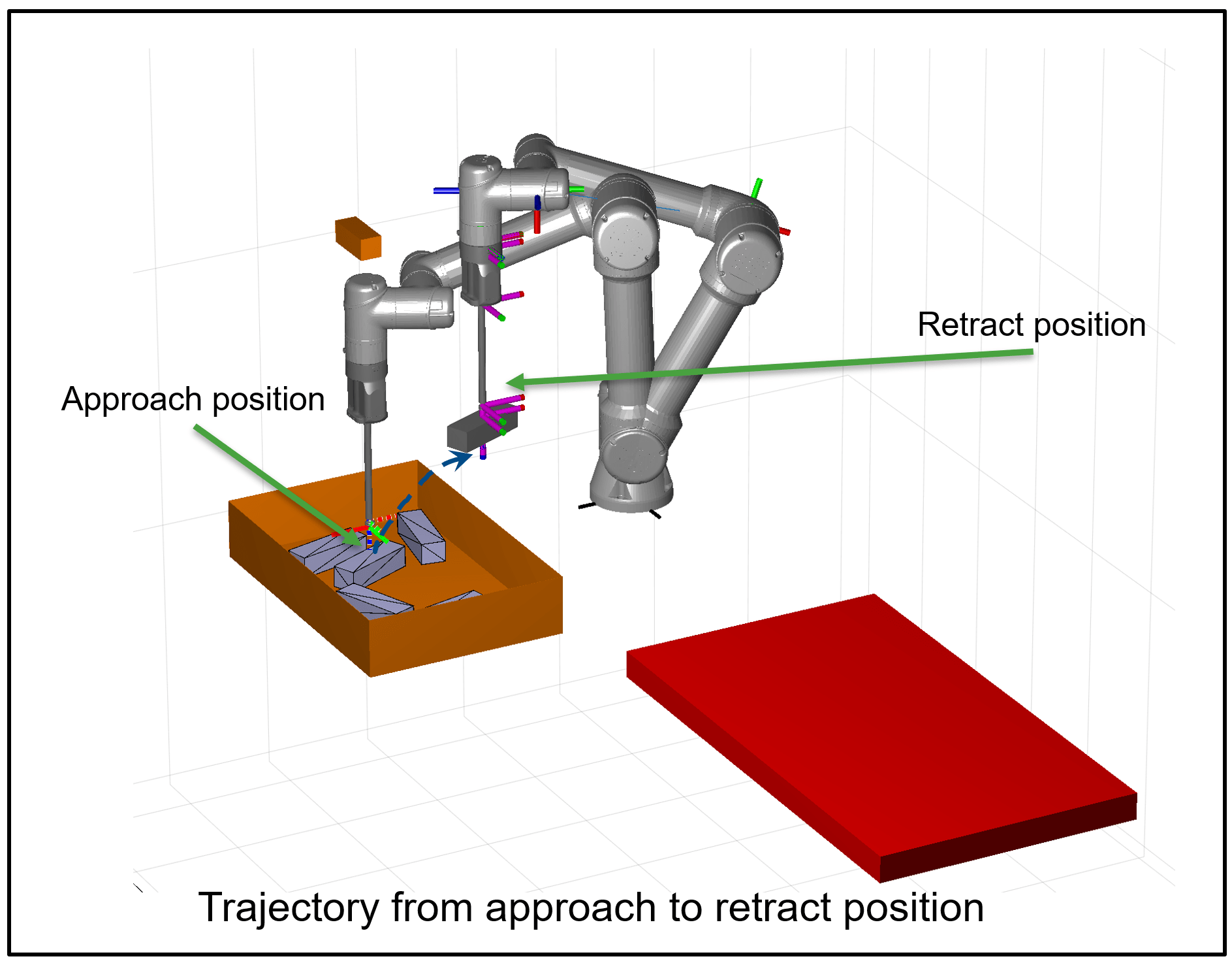
During the planning process, the robot collision model is also modified to include the part attached at the end of the gripper. If this is not done, the planner might give a trajectory that may result in the part hitting the walls of the bin, even though the gripper does not hit the walls.
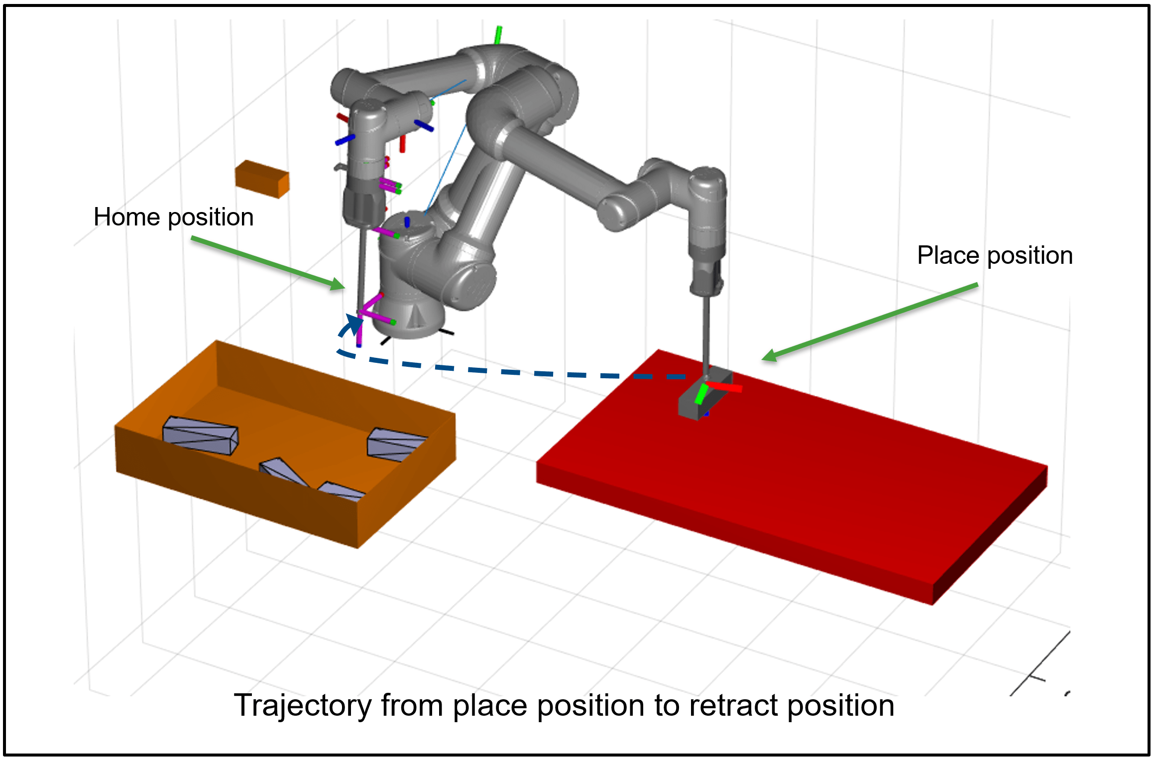
Place
If you know the place configuration, you can remove inverse kinematics solver and use preconfigured joint configurations instead, along with modifying the last joint based on the part's orientation. This reduces the computation time and cycle time.

Note: It is important to give a good initial guess to the inverse kinematics solver. Because we know the approximate drop location, it is relatively easy to come up with a very close initial guess for the drop location.
Reset
This motion allows hard reset of all joint angles to the preferred range before starting the next cycle. It helps in keeping the motion of the robot predictable and reliable.
Part Selection Algorithm
From the available parts to pick, the algorithm calculates distance between center of the part and the center of the bin. The part with the least distance from the bin's center is selected for the next pick-place cycle.
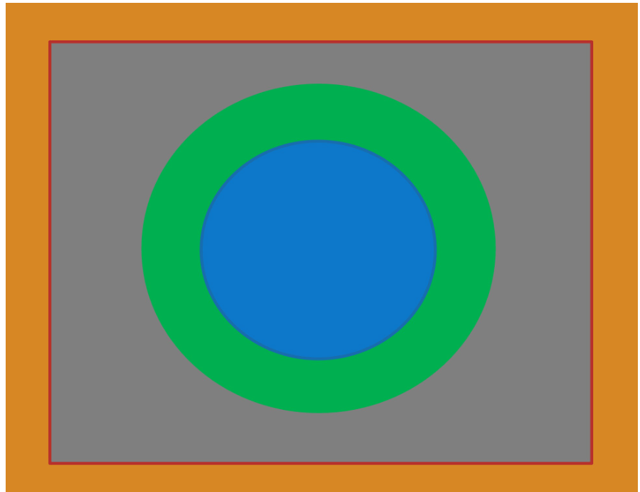
Scheduling of Planner Parameters
Blue : Cluttered environment, move carefully
Green : Less cluttered environment, can have bigger steps
Grey : Almost empty environment, motion is highly restricted, take large steps towards center
Trajectory Generation Using contopptraj
The final section of the planner uses the interpolated plan to generate q, qd and qdd commands for the real-world use case. The motion is divided into three sections.
Home to Pick - Trajectory Control
Pick to Place - Trajectory Control
Place to Home - Joint angle Control
The trajectories are generated using contopptraj, which provides constrained time optimal trajectories. The Pick to Place trajectory is generated by combining two separate plans. Due to this, the commanded end-effector velocity has a certain dip at the retract location. In the current implementation, this is handled by providing a normalized time allocation to Pick to Retract and Retract to Place based on the distance in joint space, and using this as the initial time guess to formulate piecewise polynomial with spline interpolation.
Motion Planning and Goal Execution
Start planning for the pick and place of the each object one by one.
RemainingParts = numberOfParts;
Create a goal frame object for further visualization.
goalFrame = robotics.manip.internal.workspaceGoalRegion.FrameVisual;
Run a loop for each available parts.
for p = 1:numberOfParts
    disp("Starting computation for approach trajectory");
    %%%%%% Approach trajectory %%%%%%

    % Define Goal Region
    goalRegion = workspaceGoalRegion(ur5e.BodyNames{end});

    % Add bounds for the goal region
    goalRegion.Bounds(1, :) = [0 0];  % X Bounds
    goalRegion.Bounds(2, :) = [0 0];  % Y Bounds
    goalRegion.Bounds(3, :) = [0 0];  % Z Bounds
    goalRegion.Bounds(4, :) = [0 0];  % Rotation about the Z-axis
    goalRegion.Bounds(5, :) = [0 0];  % Rotation about the Y-axis
    goalRegion.Bounds(6, :) = [0 0];  % Rotation about the X-axis

    % Select Part to pick using the part selection algorithm (It selects
    % the nearset part to the bin center point)
    [RefPose,partID,goalZoffset] = exampleHelperSelectPart(partGT,binCenterPosition);

    % Create goal region based on part position and its reference pose
    goalRegion.ReferencePose = trvec2tform(RefPose);
    goalRegion.ReferencePose(1:3,1:3) = eul2rotm([0 deg2rad(binRotation) 0]);
    goalRegion.EndEffectorOffsetPose = trvec2tform([0 0 goalZoffset]);
    goalRegion.EndEffectorOffsetPose = ...
        goalRegion.EndEffectorOffsetPose*eul2tform([0 pi 0],"ZYX");

    % Visualize the goal region for the approach
    figure(f1);
    hold on
    show(goalRegion);
    drawnow;

    % Create RRT planner using robot rigid body tree and the available
    % collision environment
    planner = manipulatorRRT(ur5e,env);

    % Set planner parameters
    planner.MaxConnectionDistance = 0.1;
    planner.ValidationDistance = 0.1;
    planner.SkippedSelfCollisions = 'parent';
    numIter = 20;

    % plan approach trajectory and compute path
    path = plan(planner,homePosition,goalRegion);

    % Compute short and interpolated path using the computed path
    shortPath = path;
    interpConfigurations = interpolate(planner,shortPath);
    cumulativePath{1} = interpConfigurations;

    % Show animation of the interpolated path
    if showAnimation
        rateObj = rateControl(30);
        for i = 1 : size(interpConfigurations)
            show(ur5e,interpConfigurations(i,:),'PreservePlot',false,'Frames','off','Collisions','off','Visuals','on','FastUpdate',true);
            drawnow
            waitfor(rateObj);
        end
    end
    hold off

    endEffectorApproachTransform = getTransform(ur5e,interpConfigurations(end,:),ur5e.BodyNames{end});
    eulerAtEndEffector = tform2eul(endEffectorApproachTransform);

    % Add part as a collision box with the robot end-effector tool
    ur5e = exampleHelperAttachPart(ur5e,-deg2rad(partGT(partID,4))+eulerAtEndEffector(1)+pi);

    % Remove part from the collision environment (remove part from the bin
    % as it attached to the robot end-effector tool)
    index = false(1,length(env));
    index(7+partID) = true;
    env(index) = [];

    %%%%%% Retract trajectory %%%%%%
    disp("Starting computation for retract trajectory")

    % Update the Planner for the modified robot and collision environment
    planner = manipulatorRRT(ur5e,env);

    % Update the planner parameters based on the distance of the object to
    % the center of the bin. Below code set the planner parameter based on
    % the environment complexity to optimize the planning computation
    dist = norm(partGT(partID,1:2) - binCenterPosition(1:2));
    shortFlag = false;
    if dist < planRadius1
        planner.MaxConnectionDistance = 0.05;
        planner.ValidationDistance = planner.MaxConnectionDistance/4;
    elseif dist >  planRadius2
        planner.MaxConnectionDistance = 0.15;
        planner.ValidationDistance = planner.MaxConnectionDistance/2;
        shortFlag = true;
    else
        planner.MaxConnectionDistance = 0.1;
        planner.ValidationDistance = planner.MaxConnectionDistance/3;
        shortFlag = true;
    end
    planner.SkippedSelfCollisions='parent';
    planner.IgnoreSelfCollision = true;

    % Compute the end pose for the retract based on the available parameters
    % using a goal region. If you have computed this once then you can set
    % "isDesign" to false and use the pre-computed configuration to save
    % the computation time.
    if isDesign
        % Define Goal Region
        goalRegion = workspaceGoalRegion(ur5e.BodyNames{end});
        goalRegion.ReferencePose(1:3,1:3) = endEffectorApproachTransform(1:3,1:3);

        goalRegion.Bounds(1, :) = [0 0];  % X Bounds
        goalRegion.Bounds(2, :) = [0 0];  % Y Bounds
        goalRegion.Bounds(3, :) = [0 0];  % Z Bounds
        goalRegion.Bounds(4, :) = [0 0];  % Rotation about the Z-axis
        goalRegion.Bounds(5, :) = [0 0];  % Rotation about the Y-axis
        goalRegion.Bounds(6, :) = [0 0];  % Rotation about the X-axis

        goalRegion.ReferencePose(1:3,4) = [binCenterPosition(1)-0.18 binCenterPosition(2) 0.22]';
        goalRegion.EndEffectorOffsetPose = trvec2tform([0 0 0]);
        goalRegion.EndEffectorOffsetPose = ...
            goalRegion.EndEffectorOffsetPose*eul2tform([0 0 0],"ZYX");

        % Show goal region
        hold on;
        show(goalRegion);
        drawnow;

        % Compute path for retract based on the given goal region
        path = plan(planner,interpConfigurations(end,:),goalRegion);
    else
        % Pre-computed retract goal configuration
        goalConfigurarion = [-0.2240   -1.3443    1.2348   -1.4613   -1.5708    1.3468];

        % Show goal frame
        goalFrame.Pose = getTransform(ur5e,goalConfigurarion,ur5e.BodyNames{end});
        hold on;
        show(goalFrame,gca);
        drawnow;

        % Compute path for retract based on the given goal configuration
        path = plan(planner,interpConfigurations(end,:),goalConfigurarion);
    end

    % Compute the short and interpolated path
    if shortFlag
        shortPath = shorten(planner,path,numIter);
        interpConfigurations = interpolate(planner,shortPath);
    else
        shortPath = path;
        interpConfigurations = interpolate(planner,shortPath);
    end
    cumulativePath{2} = interpConfigurations;

    % Delete Goal Region from the figure
    delete(findobj(f1,'type', 'hgtransform'));
    hold on;

    if isDesign
        show(goalRegion);
    else
        show(goalFrame,gca);
    end

    % Delete the part from the figure
    pt = findobj(f1,'type', 'patch','Tag','part');

    % Delete Patch
    delete(pt((RemainingParts - partID + 1)));

    % Show animation of the interp configuration for retract trajectory
    if showAnimation
        rateObj = rateControl(60);
        for i = 1 : 5 : size(interpConfigurations)
            show(ur5e,interpConfigurations(i,:),'PreservePlot',false,'Frames','off','Collisions','off','Visuals','on','FastUpdate',true);
            waitfor(rateObj);
        end
    end

    % Show robor last frame
    show(ur5e,interpConfigurations(end,:),'PreservePlot',false,'Frames','off','Collisions','off','Visuals','on','FastUpdate',true);

    %%%%%% Place trajectory %%%%%%
    % Compute end pose for the placing the object
    if isDesign
        % Fixed End-Position so using IK instead of the work space goal region
        targetPoseAngle = [-deg2rad(partGT(partID,4))+eulerAtEndEffector(1)-pi/2 pi 0];
        targetPoseXYZ = [0 0.7 0.01+partheight];
        targetPose = trvec2tform(targetPoseXYZ)*eul2tform(targetPoseAngle,"ZYX");
        goalFrame.Pose = targetPose;

        % Create IK object and set parameters
        ik = inverseKinematics('RigidBodyTree',ur5e);
        ik.SolverParameters.AllowRandomRestart = false;
        ik.SolverParameters.GradientTolerance = 1e-13;
        ik.SolverParameters.MaxTime = 5;

        weights = [1 1 1 1 1 1]; % Weights

        % Set favorable initial guess
        initialGuess = [1.3792  -1.0782    1.2490   -1.7416   -1.5708    1.7333];

        % Compute IK solution for target pose
        [configSoln,solnInfo] = ik(ur5e.BodyNames{end},targetPose,weights,initialGuess);

        % Check for pose threshold. If condition does not satisfies then
        % compute IK again with random restart
        if solnInfo.PoseErrorNorm > poseThr
            ik.SolverParameters.MaxTime = 10;
            ik.SolverParameters.AllowRandomRestart = true;

            [configSoln,solnInfo] = ik(ur5e.BodyNames{end},targetPose,weights,initialGuess);

            if solnInfo.PoseErrorNorm > poseThr
                warning("IK Failure");
                configSoln = [0.7950 -0.5093 0.2500 -1.3115 -1.5708 0];
            end

            planner.EnableConnectHeuristic = false;
            planner.SkippedSelfCollisions='parent';
            planner.IgnoreSelfCollision = true;
        end
    else
        % Fixed joint configuration based on previous analysis
        configSoln = [1.3792  -1.0821    1.2291   -1.7178   -1.5708    wrapToPi(deg2rad(partGT(partID,4)+placeAngleOffset))];
        goalFrame.Pose = getTransform(ur5e,configSoln,ur5e.BodyNames{end});
    end


    % Parameters for the planner for the place trajectory
    planner.MaxConnectionDistance = 0.5;
    planner.ValidationDistance = planner.MaxConnectionDistance/2;

    % Show the place configuration with the robot in rigid body tree
    % environment with goal frame
    figure(f1);
    hold on
    show(goalFrame,gca);
    drawnow;

    % Compute path, short path and interpolated path for the place
    path = plan(planner,interpConfigurations(end,:),configSoln);
    shortPath = shorten(planner,path,numIter);
    interpConfigurations = interpolate(planner,shortPath);
    cumulativePath{3} = interpConfigurations;

    % Delete Goal Region from the figure
    delete(findobj(f1,'type', 'hgtransform'));
    hold on;
    show(goalFrame,gca);

    % Show animation of the interpolated configuration for place trajectory
    if showAnimation
        rateObj = rateControl(30);
        for i = 1 : size(interpConfigurations)
            show(ur5e,interpConfigurations(i,:),'PreservePlot',false,'Frames','off','Collisions','off','Visuals','on','FastUpdate',true);
            waitfor(rateObj);
        end
    end

    % Delete Part from the body after placing the object (Modify the robot
    % rigid body tree environment)
    removeBody(ur5e,'part');
    RemainingParts = RemainingParts - 1;

    %%%%%% Rest position %%%%%%
    % Send robot to home position after placing the object
    % Update the Planner
    planner = manipulatorRRT(ur5e,env);
    planner.MaxConnectionDistance = 1;
    planner.ValidationDistance = 0.5;
    planner.SkippedSelfCollisions = 'parent';

    path = plan(planner,interpConfigurations(end,:),homePosition);
    shortPath = shorten(planner,path,numIter);
    cumulativePath{4} = shortPath;
    interpConfigurations = interpolate(planner,shortPath);

    % Delete Robot from the figure
    delete(findobj(f1,'type', 'hgtransform'));

    if showAnimation
        rateObj = rateControl(60);
        for i = 1 : size(interpConfigurations)
            show(ur5e,interpConfigurations(i,:),'PreservePlot',false,'Frames','off','Collisions','off','Visuals','on','FastUpdate',true);
            waitfor(rateObj);
        end
    end

    %% Trajectory interpolation using contopptraj with the max acceleration and max velocity bounds
    % Robot Parameters
    maxqd = pi/2; % in rad/s
    maxqdd = deg2rad(100); % in rad/s2
    vellimits = repmat([-maxqd; maxqd],1,6);
    accellimits  = repmat([-maxqdd; maxqdd],1,6);

    % Interpolate the approach trajectory
    path1 = cumulativePath{1};
    [q,qd,qdd,t] = contopptraj(path1',vellimits',accellimits',NumSamples=size(path1,1)*10);

    % Show animation of final interpolated trajectory if flag is enable
    if showAnimationTraj
        hold on;
        rateObj = rateControl(30);
        for i = 1 : size(q,2)
            show(ur5e,q(:,i)','PreservePlot',false,'Frames','off','Collisions','off','Visuals','on','FastUpdate',true);
            waitfor(rateObj);
        end
    end

    % Interpolate retract + place trajectory (Note that this is combine
    % trajectory)
    path21 = cumulativePath{2};
    path22 = cumulativePath{3};

    % Normalized distance in joint space
    dist_joints_1 = norm(cumulativePath{2}(1,:)-cumulativePath{2}(end,:));
    dist_joints_2 = norm(cumulativePath{3}(1,:)-cumulativePath{3}(end,:));
    dist_total = dist_joints_1 + dist_joints_2;

    % Combine both trajectories
    path2=[path21;path22];
    initialGuessPath2 = [linspace(0,dist_joints_1/dist_total,size(path21,1)) linspace(dist_joints_1/dist_total,1,size(path22,1))];

    % Remove Duplicate Rows
    path2(size(path21,1),:) = [];
    initialGuessPath2(size(path21,1)) = [];

    % Compute piece wise polynomial
    pp = interp1(initialGuessPath2,path2,'spline','pp');

    % Apply contopptraj for retract + place trajectory
    [q,qd,qdd,t] = contopptraj(pp,vellimits',accellimits',NumSamples=size(path2,1)*10);

    % Show animation of the trajectory
    if showAnimationTraj
        hold on;
        rateObj = rateControl(30);
        for i = 1 : size(q,2)
            show(ur5e,q(:,i)','PreservePlot',false,'Frames','off','Collisions','off','Visuals','on','FastUpdate',true);
            waitfor(rateObj);
        end
    end

    % Delete Part Ground Truth
    partGT(partID,:) = [];
end
Starting computation for approach trajectory
Starting computation for retract trajectory
Starting computation for approach trajectory
Starting computation for retract trajectory
Starting computation for approach trajectory
Starting computation for retract trajectory
Starting computation for approach trajectory
Starting computation for retract trajectory
Starting computation for approach trajectory
Starting computation for retract trajectory