Log Simulink Signals to DataFlash Log on ArduPilot Autopilots
R2026bThis example shows how to log custom Simulink® signals to an ArduPilot® DataFlash log by using the DataFlash Log block from the UAV Toolbox Support Package for ArduPilot Autopilots. You deploy the model to supported ArduPilot hardware, run the model on the target, retrieve the generated .bin log file from the vehicle, and analyze the logged data in MATLAB®.
Prerequisites
1. If you are new to Simulink, watch the Simulink Quick Start video.
2. If you have not done so already, complete the steps in Install UAV Toolbox Support Package for ArduPilot Autopilots in Windows.
DataFlash Log Overview
ArduPilot stores onboard telemetry data in a binary format known as DataFlash logs. These logs are written to the autopilot's onboard storage (such as an SD card or internal flash memory) and contain timestamped records of sensor readings, control outputs, navigation data, and user-defined messages.
DataFlash logs are the primary mechanism for post-flight analysis in ArduPilot. Each log entry is identified by a message type (for example, ATT for attitude, GPS for GPS data, or custom user-defined types). The logging system supports:
High-rate onboard logging independent of telemetry bandwidth.
Custom message types for user-defined signals.
Conditional logging based on vehicle state (armed/disarmed).
Retrieval via USB, MAVLink, or direct SD card access.
For more information about the DataFlash logging system, see the ArduPilot DataFlash Logs documentation.
Open Model
Open the DataFlashLog.slx model.
modelName = "DataFlashLog";
open_system(modelName)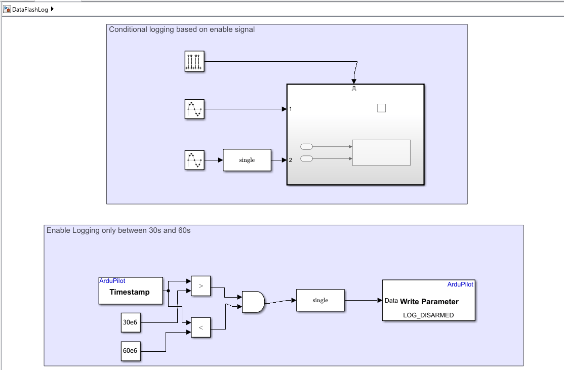
Model Overview
The model contains two main functional areas:
Conditional logging based on enable signal — An Enabled Subsystem that writes signals to the DataFlash log only when the enable condition is true.
Enable Logging only between 30s and 60s — Logic that writes the
LOG_DISARMEDparameter to enable logging when the vehicle is disarmed, active only within a specific time window.
Conditional Logging with Enabled Subsystem
The DataFlash Log block is placed inside an Enabled Subsystem. This design pattern allows you to conditionally log data based on an enable signal. When the enable input is true (nonzero), the subsystem executes and the DataFlash Log block writes the input signals to the onboard log. When the enable input is false (zero), no data is written.
Inside the Enabled Subsystem, the DataFlash Log block (configured with the message name LOG1, which identifies this custom log entry in the DataFlash file) accepts two input signals:
Sig1 — First signal to log.
Sig2 — Second signal to log.
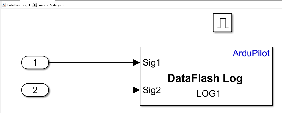
The signals connected to the DataFlash Log block are written as a custom message type in the DataFlash log file. You can configure the block to define the message name and field labels that appear when you analyze the log.
Enabling Logging When Disarmed
By default, ArduPilot writes DataFlash logs only when the vehicle is armed. For testing and development, you can log data without arming the vehicle. The model demonstrates how to temporarily enable logging while disarmed by writing the LOG_DISARMED parameter.
The lower section of the model implements this logic:
The ArduPilot Timestamp block provides the current time in microseconds.
Comparison blocks check whether the timestamp is between 30 seconds (
30e6μs) and 60 seconds (60e6μs).A logical AND combines both conditions and converts the result to
single.The ArduPilot Write Parameter block writes the value to the
LOG_DISARMEDparameter.
When the timestamp is between 30 and 60 seconds after boot, LOG_DISARMED is set to 1 (enabled). Outside this window, it is set to 0 (disabled).
Logging behavior
The DataFlash Log block writes custom signals into the ArduPilot DataFlash .bin log file generated on the target. You can later import that log file into MATLAB by using the ardupilotreader object, which reads ArduPilot DataFlash log files and exposes messages, parameters, and logged output for analysis.
Run the Model and Observe Results
After you complete the hardware and model configuration:
On the Hardware tab, in the Mode section, click Run on board, click the drop-down and select Run on board (External mode). If you see Connected IO selected instead of Run on board, click on it and choose Run on board (External mode)
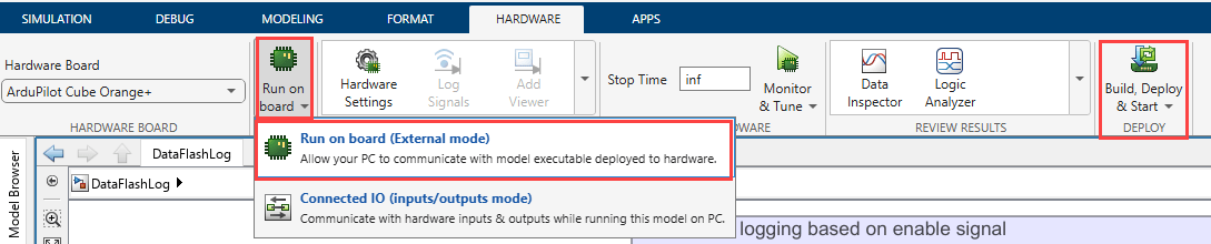
2. Click Build, Deploy & Start. After deployment, the algorithm runs autonomously on the hardware.
After you deploy the model and run it on the target, the autopilot generates a DataFlash log file that contains the custom signals logged by the DataFlash Log block. Because the block is inside an enabled subsystem, the custom signals are logged only when the enable condition is true. In this example, the model also temporarily sets LOG_DISARMED so that you can capture log data without arming the vehicle during bench testing. LOG_DISARMED enables logging before arming, while normal Copter logging begins after arming by default.
Import the downloaded .bin file into MATLAB by using ardupilotreader or the Flight Log Analyzer app to inspect the recorded signals, verify the active logging interval, and correlate the custom log data with other ArduPilot messages in the same file.
Retrieve and Analyze Log Data
Before analyzing the log data in MATLAB®, retrieve the DataFlash log (.bin) file from the ArduPilot autopilot and save it on the host computer. After retrieving the log file, use the ardupilotreader object to import and analyze the logged data.
Retrieve and Analyze Logs in MATLAB
Use the UAV Toolbox APIs to download the log file from the autopilot and read the DataFlash log data into MATLAB.
Read the DataFlash Log File
Use ardupilotreader to import the .bin file:
% logObj = ardupilotreader("flight.bin");
The ardupilotreader object reads ArduPilot DataFlash log files and provides metadata such as:
Logging start and end times (
StartTime,EndTime)Available message types (
AvailableMessages— a table containingMsgName,InstanceID,StartTimestamp,LastTimestamp, andNumMessages)Total number of messages (
NumMessages)
Read Logged Messages
Use readMessages to retrieve messages from the log file:
% msgTbl = readMessages(logObj);
This function returns a table containing:
Message names
Instance IDs
Timestamps
Message data and formats
Read Logged Parameters
Use readParameters to extract parameter values stored in the log. This is useful for verifying that parameters such as LOG_DISARMED were written correctly:
% paramTbl = readParameters(logObj);
Read Logged Output Messages
Use readLoggedOutput to access logged output messages from the log file. This includes custom log messages written by the DataFlash Log block:
% outTbl = readLoggedOutput(logObj);
This function returns output messages (such as custom logs written using DataFlash Log blocks).
Analyze Custom Logged Messages
In this example, the DataFlash Log block is configured to write a custom message named LOG1. Use readLoggedOutput to inspect the logged output messages and identify the recorded signal values associated with the custom log entry. Review the logged signal values and timestamps captured in the custom log entry.
% Read custom logged output messages
outTbl = readLoggedOutput(logObj);
% Display a subset of the logged data
head(outTbl)
Plot Logged Signals
Plot the logged signal values to verify that signals are recorded only while the Enabled Subsystem executes.
% Example plot workflow
plot(outTbl.Timestamp,outTbl.Sig1)
hold on
plot(outTbl.Timestamp,outTbl.Sig2)
grid on

xlabel("Time")
ylabel("Signal Value")
legend("Sig1","Sig2")
title("Custom LOG1 Signals")
The logged interval should correspond to the enable condition configured in the model. In this example, logging is enabled only during the specified time window.
Visualize Logs Using Flight Log Analyzer
You can also analyze the .bin file interactively:
Open the Flight Log Analyzer app.
Select Import > From BIN.
Load the DataFlash log file.
Plot signals and inspect time intervals.
Other Things to Try
Change the enable logic so that the model logs signals in a different time interval.
Log additional signals by adding input ports to the enabled subsystem and connecting them to the DataFlash Log block.
Remove the temporary
LOG_DISARMEDworkflow and test the example using normal armed logging.Use
readParametersto confirm whenLOG_DISARMEDchanged during execution.

