Read GPS Data from PX4 Autopilot
This example shows you how to read GPS data from a PX4 autopilot, in Simulink, using the UAV Toolbox Support Package for PX4 Autopilots.
Prerequisites
If you are new to Simulink, watch the Simulink Quick Start video.
Complete the UAV Toolbox Support Package for PX4 Autopilots Setup and Configuration.
You must run this example in an area that has GPS signal reception.
Required Hardware
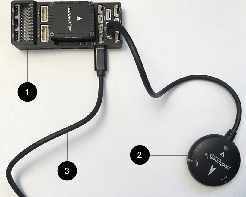
PX4 autopilot — This example uses the Pixhawk 6x autopilot. For a list of supported PX4 autopilots, see Supported PX4 Autopilots.
GPS module — This example uses a Pixhawk 4 GPS module.
USB cable
Model Overview
Open the px4demo_readGPS.slx Simulink model
open_system("px4demo_readGPS.slx")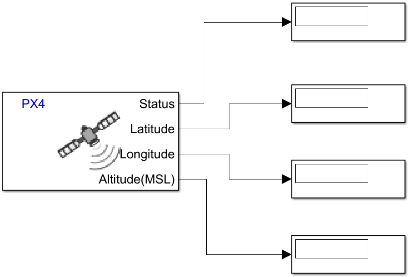
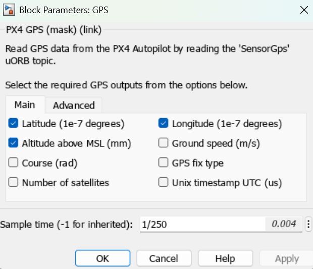
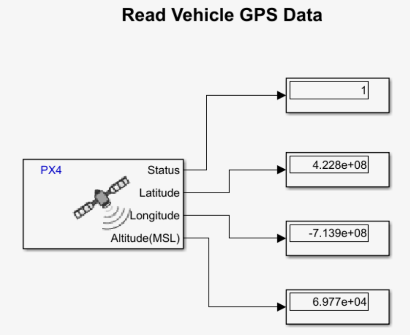
The px4demo_readGPS.slx Simulink model uses the GPS block to read the vehicle_gps_position uORB topic from the PX4 autopilot. In this example, the block has been configured to output the latitude, longitude, and altitude of the PX4 autopilot, in addition to its GPS status, by selecting the Latitude (1e-7 degrees), Longitude (1e-7 degrees), and Altitude above MSL (mm) parameters.
Configure Simulink Model
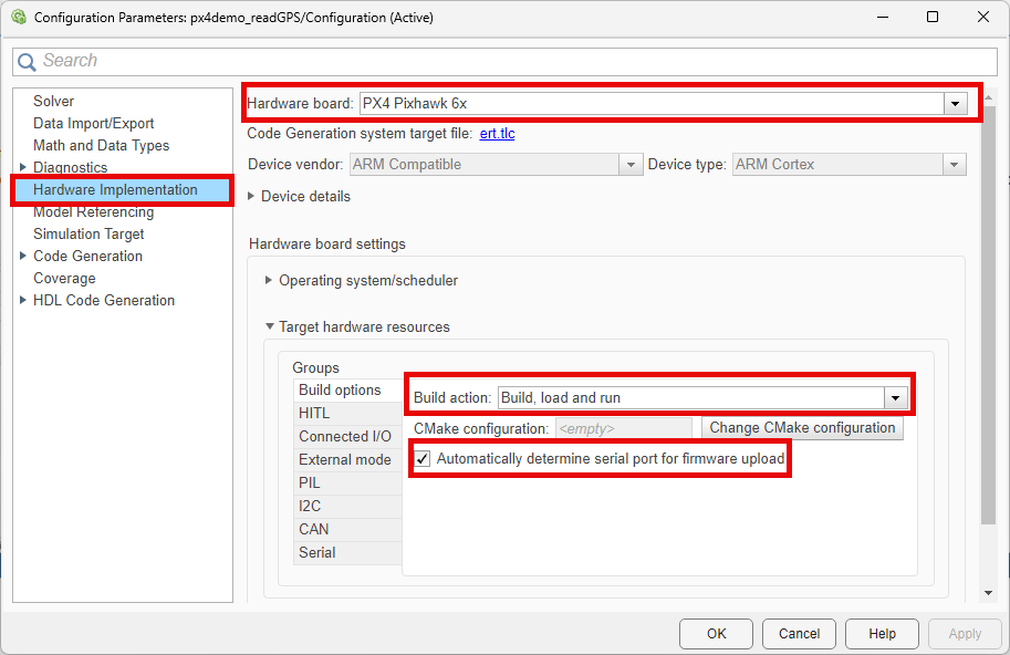
On the Simulink Toolstrip, on the Hardware tab, click Hardware Settings ![]() . Select the Hardware Implementations tab, and verify these options:
. Select the Hardware Implementations tab, and verify these options:
Hardware board specifies which PX4 autopilot to use to run the model. This example uses the
PX4 Pixhawk 6x.Under Target hardware resources, select the Build options tab of the Groups pane. Note that the Build action option is set to
Build, load and run, and Automatically determine serial port for firmware upload has been selected.
Select the External mode tab of the Groups pane, the Use the same host serial port for External mode as used for firmware upload option has been selected.
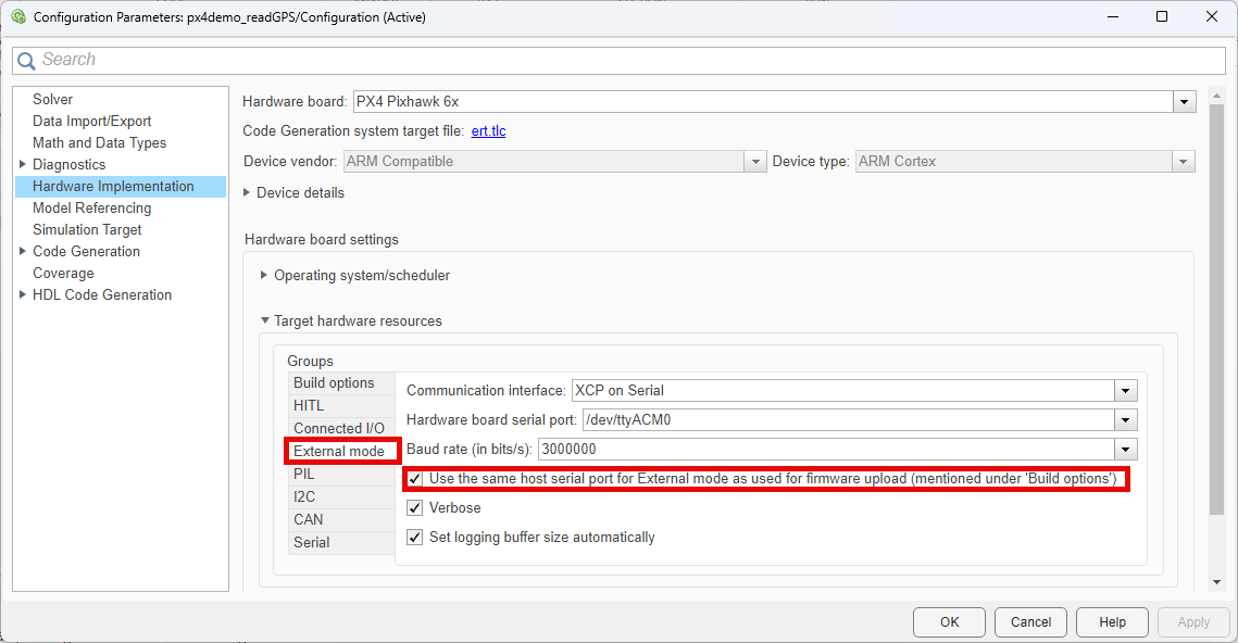
Click OK to save any changes and close the Configuration Parameters window.
Run Simulink Model in Connected IO mode
Before running the Simulink model, connect the PX4 autopilot to your computer by using the USB cable. Additionally, ensure that the GPS module is able to receive GPS signal by placing the module in an open environment or close to an open window.
To run the px4demo_readGPS.slx model in connected IO mode:
1. On the Hardware tab of the Simulink Toolstrip, in the Mode pane section, verify that the button says Connected IO. If it says Run on board, select it and click Connected IO (inputs/outputs mode)
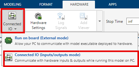
2. In the Run on Computer section, click Run with IO ![]() .
.
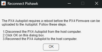
When you run this Simulink model for the first time, or if you run it after changing to a different PX4 autopilot, Simulink builds the Connected I/O firmware for the PX4 autopilot and prompts you to reconnect the PX4 autopilot. When the dialog box that instructs you to reconnect the PX4 autopilot appears, disconnect the PX4 autopilot from your computer, click OK, and then reconnect the PX4 autopilot to your computer.
The Simulink model now displays the GPS status, latitude, longitude, and altitude of the PX4 autopilot.
To stop the Simulink model, click Stop![]() on the toolstrip.
on the toolstrip.
To instead run the Simulink model in monitor and tune mode, follow these steps:
On the Hardware tab of the Simulink Toolstrip, in the Mode section, click the button and select Run on board (External mode).
In the Run on Hardware section, click Monitor & Tune.
he model generates code to run on the PX4 autopilot. When the dialog box that instructs you to reconnect the PX4 autopilot appears, disconnect the PX4 autopilot from your computer, click OK, and then reconnect the PX4 autopilot to your computer.