Convert Camera Control Signals to pixelcontrol Format
This example shows how to convert Camera Link® signals to the pixelcontrol structure, invert the pixels with a Vision HDL Toolbox™ object, and convert the control signals back to the Camera Link format.
Vision HDL Toolbox blocks and objects use a custom streaming video format. If your system operates on streaming video data from a camera, you must convert the camera control signals into this custom format. Alternatively, if you integrate Vision HDL Toolbox algorithms into existing design and verification code that operates in the camera format, you must also convert the output signals from the Vision HDL Toolbox design back to the camera format.
You can generate HDL code from the three functions in this example. To create local copies of all the files in this example, so you can view and edit them, click the Open Script button.
Create Input Data in Camera Link Format
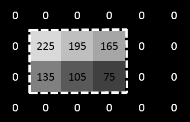
The Camera Link format consists of three control signals: F indicates the valid frame, L indicates each valid line, and D indicates each valid pixel. For this example, create input vectors in the Camera Link format to represent a basic padded video frame. The vectors describe this 2-by-3, 8-bit grayscale frame. In the figure, the active image area is in the dashed rectangle, and the inactive pixels surround it. The pixels are labeled with their grayscale values.
![]()
F = logical([0,0,0,0,0,0,0,1,1,1,1,1,1,1,1,1,0,0,0,0,0,0,0,0]);
L = logical([0,0,0,0,0,0,0,1,1,1,0,0,0,1,1,1,0,0,0,0,0,0,0,0]);
D = logical([0,0,0,0,0,0,0,1,1,1,0,0,0,1,1,1,0,0,0,0,0,0,0,0]);
pixel = uint8([0,0,0,0,0,0,0,30,60,90,0,0,0,120,150,180,0,0,0,0,0,0,0,0]);
Design Vision HDL Toolbox Algorithm
Create a function to invert the image using Vision HDL Toolbox algorithms. The function contains a System object that supports HDL code generation. This function expects and returns a pixel and associated control signals in Vision HDL Toolbox format.
function [pixOut,ctrlOut] = Invert(pixIn,ctrlIn)

persistent invertI;
if isempty(invertI)
    tabledata = linspace(255,0,256);
    invertI = visionhdl.LookupTable(uint8(tabledata));
end

[pixOut,ctrlOut] = invertI(pixIn,ctrlIn);
Convert Camera Link Control Signals to pixelcontrol Format
Write a custom System object to convert Camera Link signals to the Vision HDL Toolbox control signal format. The object converts the control signals, and then calls the pixelcontrolstruct function to create the structure expected by the Vision HDL Toolbox System objects. This code snippet shows the logic to convert the signals.
  ctrl = pixelcontrolstruct(obj.hStartOutReg,obj.hEndOutReg,...
                       obj.vStartOutReg,obj.vEndOutReg,obj.validOutReg);
vStart = obj.FReg && ~obj.FPrevReg; vEnd = ~F && obj.FReg; hStart = obj.LReg && ~obj.LPrevReg; hEnd = ~L && obj.LReg;
  obj.vStartOutReg = vStart;
  obj.vEndOutReg = vEnd;
  obj.hStartOutReg = hStart;
  obj.hEndOutReg = hEnd;
  obj.validOutReg = obj.DReg;
The object stores the input and output control signal values in registers. vStart goes high for one cycle at the start of F. vEnd goes high for one cycle at the end of F. hStart and hEnd are derived similarly from L. The object returns the current value of ctrl each time you call it.
This processing adds two cycles of delay to the control signals. The object passes through the pixel value after matching delay cycles. For the complete code for the System object, see CAMERALINKtoVHT_Adapter.m.
Convert pixelcontrol to Camera Link
Write a custom System object to convert Vision HDL Toolbox signals back to the Camera Link format. The object calls the pixelcontrolsignals function to flatten the control structure into its component signals. Then it computes the equivalent Camera Link signals. This code snippet shows the logic to convert the signals.
[hStart,hEnd,vStart,vEnd,valid] = pixelcontrolsignals(ctrl);
  Fnew = (~obj.FOutReg && vStart) || (obj.FPrevReg && ~obj.vEndReg);
  Lnew = (~obj.LOutReg && hStart) || (obj.LPrevReg && ~obj.hEndReg);
  obj.FOutReg = Fnew;
  obj.LOutReg = Lnew;
  obj.DOutReg = valid;
The object stores the input and output control signal values in registers. F is high from vStart to vEnd. L is high from hStart to hEnd. The object returns the current values of FOutReg, LOutReg, and DOutReg each time you call it.
This processing adds one cycle of delay to the control signals. The object passes through the pixel value after a matching delay cycle. For the complete code for the System object, see VHTtoCAMERALINKAdapter.m.
Create Conversion Functions That Support HDL Code Generation
Wrap the converter System objects in functions, similar to Invert, so you can generate HDL code for these algorithms.
function [ctrl,pixelOut] = CameraLinkToVisionHDL(F,L,D,pixel)
% CameraLink2VisionHDL : converts one cycle of CameraLink control signals
% to Vision HDL format, using a custom System object.
% Introduces two cycles of delay to both ctrl signals and pixel data.

persistent CL2VHT;
if isempty(CL2VHT)
    CL2VHT = CAMERALINKtoVHT_Adapter();
end

[ctrl,pixelOut] = CL2VHT(F,L,D,pixel);
See CameraLinkToVisionHDL.m, and VisionHDLToCameraLink.m.
Write a Test Bench
To invert a Camera Link pixel stream using these components, write a test bench script that:
Preallocates output vectors to reduce simulation time
Converts the Camera Link control signals for each pixel to the Vision HDL Toolbox format
Calls the
Invertfunction to flip each pixel valueConverts the control signals for that pixel back to the Camera Link format
[~,numPixelsPerFrame] = size(pixel);
pixOut = zeros(numPixelsPerFrame,1,'uint8');
pixel_d = zeros(numPixelsPerFrame,1,'uint8');
pixOut_d = zeros(numPixelsPerFrame,1,'uint8');
DOut = false(numPixelsPerFrame,1);
FOut = false(numPixelsPerFrame,1);
LOut = false(numPixelsPerFrame,1);
ctrl = repmat(pixelcontrolstruct,numPixelsPerFrame,1);
ctrlOut = repmat(pixelcontrolstruct,numPixelsPerFrame,1);

for p = 1:numPixelsPerFrame
  [pixel_d(p),ctrl(p)] = CameraLinkToVisionHDL(pixel(p),F(p),L(p),D(p));
  [pixOut(p),ctrlOut(p)] = Invert(pixel_d(p),ctrl(p));
  [pixOut_d(p),FOut(p),LOut(p),DOut(p)] = VisionHDLToCameraLink(pixOut(p),ctrlOut(p));
end
View Results
The resulting vectors represent this inverted 2-by-3, 8-bit grayscale frame. In the figure, the active image area is in the dashed rectangle, and the inactive pixels surround it. The pixels are labeled with their grayscale values.

If you have a DSP System Toolbox™ license, you can view the vectors as signals over time using the Logic Analyzer. This waveform shows the pixelcontrol and Camera Link control signals, the starting pixel values, and the delayed pixel values after each operation. Run NewCustomCtrlSignals_LogicAnalyzer.m to generate this logic analyzer.

See Also
pixelcontrolstruct | pixelcontrolsignals