记录并回放 CAN FD 报文
以下示例说明如何使用 Simulink® 中的 MathWorks® 虚拟 CAN FD 通道记录和回放 CAN FD 报文。您可以更新此模型以连接到您的系统上支持的硬件。
从示例文件夹中的 SourceFDMsgs.mat 文件加载保存的 CAN FD 报文。该文件包含 CAN FD 报文,这些报文表示绕试车道一周的 90 秒驾驶周期。
load SourceFDMsgs.mat检查包含 CAN FD 报文的时间表。特别要注意,初始时间戳不为零:
startTime = seconds(canFDMsgTimetable.Time(1)) %#ok<NOPTS>startTime = 88.6176
stopTime = seconds(canFDMsgTimetable.Time(end)) %#ok<NOPTS>stopTime = 177.2310
将这些报文转换为与 CAN FD Replay 模块兼容的格式,并将其保存到一个单独的文件中。
canFDMsgs = canFDMessageReplayBlockStruct(canFDMsgTimetable);
save DriveReplayFD.mat canFDMsgs
whos
  Name                        Size               Bytes  Class        Attributes

  canFDMsgTimetable      100000x12            45411725  timetable
  canFDMsgs                   1x1              8401848  struct
  startTime                   1x1                    8  double
  stopTime                    1x1                    8  double
CAN FD Replay 模型
该模型包含:
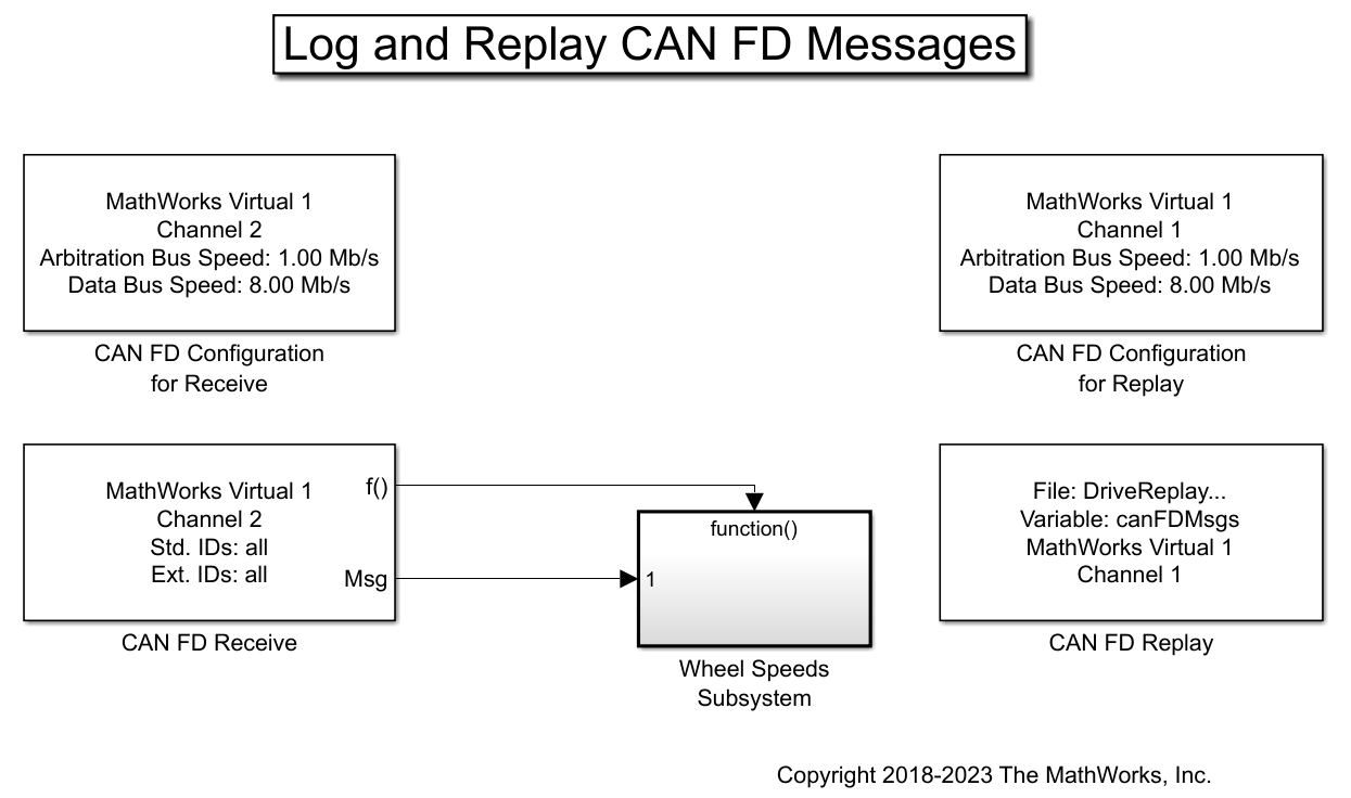
一个 CAN FD Replay 模块,用于向
MathWorks Virtual Channel 1传输报文。一个 CAN FD Receive 模块,用于通过
MathWorks Virtual Channel 2接收 CAN FD 网络上的报文。
CAN FD Receive 模块配置为阻止所有扩展 ID,并且仅允许具有标准 ID 1200 的 WheelSpeed 报文通过。

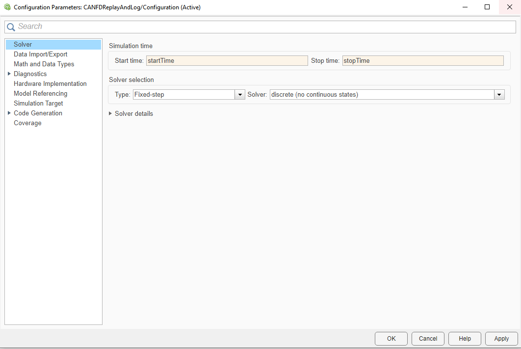
使用报文时间序列的初始和最终时间戳连贯地配置仿真开始和停止时间。为此,请选择建模选项卡,然后点击模型设置。然后,在配置参数对话框中,使用之前定义的变量 startTime 和 stopTime 设置仿真开始和停止时间。点击应用,然后关闭配置参数窗口。

通过点击运行按钮来运行仿真。
请注意诊断查看器中的警告:

该模型配置为使用定步长求解器,时间步为 0.01 秒。然而,从记录的时间序列中获得的开始和停止时间的值不是仿真时间步的整数倍。Simulink 中的默认行为是对这些值进行舍入,使它们与仿真时间步一致;它们也可以在仿真前在 MATLAB® 脚本中舍入。有关 Simulink 求解器自动参数选择的详细信息,请参阅文档页选择求解器 (Simulink)。
Wheel Speeds 子系统
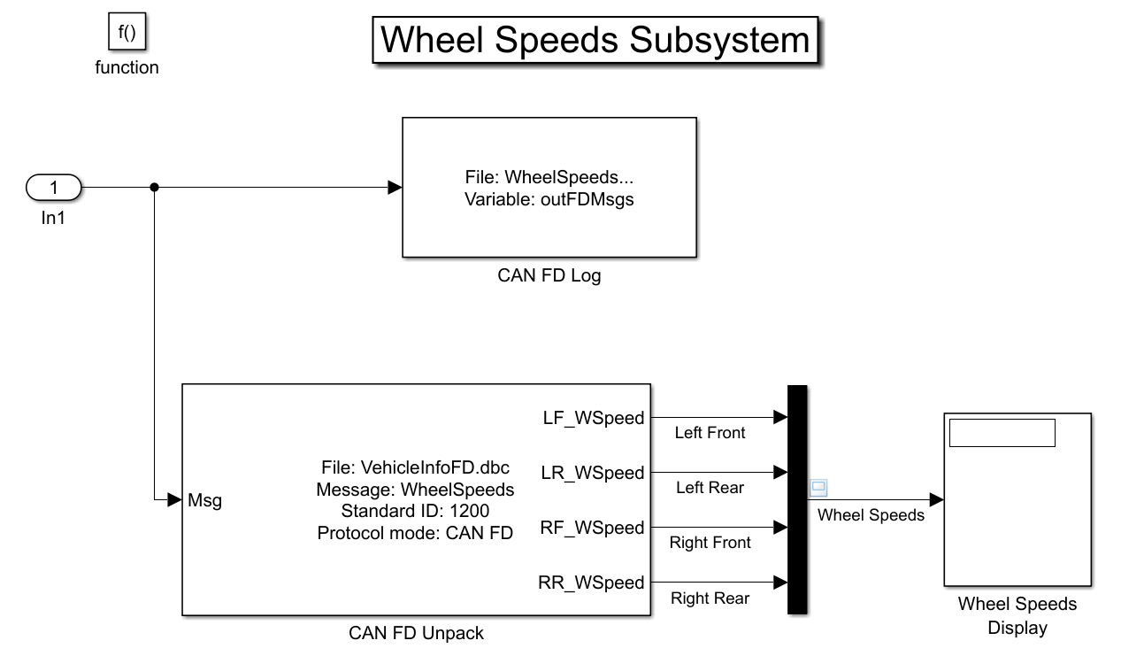
Wheel Speeds 子系统对收到的 CAN FD 报文中的轮速信息解包,并将它们绘制到示波器中。该子系统还将报文记录到一个文件中。

可视化轮速信息
示波器中的绘图显示试驾期间所有车轮的轮速。
根据计算机的配置,仿真后示波器中的信号可能为零。此结果是正常的:模型仿真和报文传输在不同线程中执行,因此并不同步。Simulink 尝试尽可能快地仿真模型,由于时间序列非常短,因此,到仿真结束时,很可能第一条报文的接收尚未完成。
要在 Simulink 中回放记录信号,更合适的方法是使用仿真调速在近实时的情况下执行模型。这样,模型的仿真大致可以记录信号的速度运行。要启用仿真调速,请点击运行 -> 仿真调速,然后选中复选框启用调速以减慢仿真。再次运行仿真并检查示波器,它现在显示适当的信号。

要了解有关仿真调速的更多信息,请访问此页:仿真调速选项 (Simulink)。
加载包含所记录报文的文件
每次运行模型时,CAN FD Log 模块都会创建一个具有唯一性的文件。在 MATLAB 命令行窗口中使用 dir 查找最新日志文件。
dir WheelSpeeds*.matWheelSpeeds_2023-Jun-20_123918.mat WheelSpeeds_2023-Jun-20_151835.mat
load WheelSpeeds_2023-Jun-20_123918.mat
whos
Name Size Bytes Class Attributes canFDMsgTimetable 100000x12 45411725 timetable canFDMsgs 1x1 8401848 struct outFDMsgs 1x1 7845516 struct startTime 1x1 8 double stopTime 1x1 8 double
转换记录的报文
使用 startTime 变量来偏移 CAN FD Log 模块中记录的时间戳。
outFDMsgs.Timestamp = startTime + outFDMsgs.Timestamp;
使用函数 canFDMessageTimetable 将仿真期间记录的报文转换为可在命令行窗口中使用的时间表。
要直接访问报文信号,请在转换中使用对应的数据库文件以及 canSignalTimetable。
db = canDatabase('VehicleInfoFD.dbc');
wheelSpeedMsgTimetable = canFDMessageTimetable(outFDMsgs, db);
wheelSpeedMsgTimetable(1:15, :)ans=15×12 timetable
Time ID Extended Name ProtocolMode Data Length DLC Signals Error Remote BRS ESI
__________ ____ ________ _______________ ____________ ______________________________ ______ ___ ____________ _____ ______ _____ _____
88.829 sec 1201 false {0×0 char } {'CAN FD'} {[ 0 0 0 0 0 0 0 0]} 8 8 {0×0 struct} false false true false
88.83 sec 1312 false {0×0 char } {'CAN FD'} {[ 250 0 200 50 0]} 5 5 {0×0 struct} false false true false
88.831 sec 512 false {0×0 char } {'CAN FD'} {[ 2 1 1 250 1 231 129 255]} 8 8 {0×0 struct} false false true false
88.832 sec 513 false {0×0 char } {'CAN FD'} {[12 103 255 255 39 16 1 255]} 8 8 {0×0 struct} false false true false
88.832 sec 533 false {0×0 char } {'CAN FD'} {[ 2 26 2 26 2 24 0 0]} 8 8 {0×0 struct} false false true false
88.832 sec 561 false {0×0 char } {'CAN FD'} {[ 15 4 255 255 0 0 0 0]} 8 8 {0×0 struct} false false true false
88.832 sec 576 false {0×0 char } {'CAN FD'} {[ 63 141 140 32]} 4 4 {0×0 struct} false false true false
88.832 sec 1616 false {0×0 char } {'CAN FD'} {[ 0]} 1 1 {0×0 struct} false false true false
88.836 sec 1200 false {'WheelSpeeds'} {'CAN FD'} {[ 39 16 39 16 39 16 39 16]} 8 8 {1×1 struct} false false true false
88.836 sec 1201 false {0×0 char } {'CAN FD'} {[ 0 0 0 0 0 0 0 0]} 8 8 {0×0 struct} false false true false
88.836 sec 1216 false {0×0 char } {'CAN FD'} {[ 163]} 1 1 {0×0 struct} false false true false
88.841 sec 512 false {0×0 char } {'CAN FD'} {[ 2 1 1 250 1 231 129 255]} 8 8 {0×0 struct} false false true false
88.842 sec 513 false {0×0 char } {'CAN FD'} {[12 103 255 255 39 16 1 255]} 8 8 {0×0 struct} false false true false
88.842 sec 533 false {0×0 char } {'CAN FD'} {[ 2 26 2 26 2 24 0 0]} 8 8 {0×0 struct} false false true false
88.843 sec 1296 false {0×0 char } {'CAN FD'} {[ 0 0 1]} 3 3 {0×0 struct} false false true false
wheelSpeedSignals = canSignalTimetable(wheelSpeedMsgTimetable);
wheelSpeedSignals(end-14:end, :)
ans=15×4 timetable
       Time       RR_WSpeed    RF_WSpeed    LR_WSpeed    LF_WSpeed
    __________    _________    _________    _________    _________

    177.31 sec       57.4        57.37        57.27        57.35
    177.32 sec      57.39        57.35         57.3        57.32
    177.33 sec      57.36        57.39         57.4        57.31
    177.33 sec      57.47        57.46        57.47        57.37
    177.34 sec      57.56        57.41        57.45        57.39
    177.35 sec      57.48        57.33        57.43         57.4
    177.36 sec      57.37        57.35        57.41        57.41
    177.37 sec      57.33        57.41        57.41        57.39
    177.37 sec      57.37        57.44        57.44        57.36
    177.38 sec      57.48        57.47        57.43        57.35
    177.39 sec       57.5        57.43         57.4        57.33
    177.4 sec       57.48        57.36        57.35        57.32
    177.41 sec      57.43        57.35        57.28        57.33
    177.42 sec      57.28         57.4        57.26        57.36
    177.43 sec      57.27        57.46        57.23        57.35
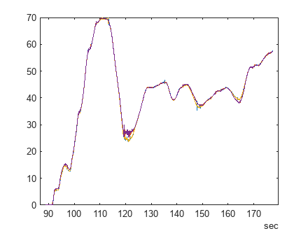
plot(wheelSpeedSignals.Time, wheelSpeedSignals{:,:});
此示例中使用了 MathWorks CAN FD 虚拟通道。但是,您可以将模型连接到其他支持的硬件。
另请参阅
工具
- 仿真调速选项 (Simulink)
主题
- 硬件接口模型中的计时
- 选择求解器 (Simulink)