Verify 5G Wireless Applications Using SystemVerilog DPI
This example shows how to use SystemVerilog DPI components to verify 5G wireless applications in an HDL environment.
The system in this example uses various 5G components and a parameterizable 5G waveform generator to validate the behavior of the Synchronization Signal Block (SSB) decoding section of the Master Information Block (MIB) recovery process.
The verification workflow includes these key benefits:
3GPP 5G New Radio (NR) standard requires deep domain expertise. Creating a standard-compliant waveform verification model can be challenging. Generating a DPI component from a Wireless HDL Toolbox™ waveform generator simplifies the testbench design process by automatically creating a standard compliant verification IP.
The parameterizable 5G waveform generator tests the DUT in different scenarios. You can reconfigure the parameters to create a series of test cases to meet coverage.
The standalone 5G DPI components generated from Simulink® and MATLAB® can be reused and integrated in customized testbenches.
The component-based workflow makes designing a standalone testbench faster. You can splice different modules in the top-level testbench to test different 5G function components.
Full functional control at the top level testbench enables component manipulation according to the process status changes. This control results in performance gains compared to a test-vector-based HDL testbench.
MIB Recovery Process
MIB recovery requires SSB detection, demodulation, and decoding. This example shows how to validate the HDL code generated by HDL Coder™ for the SSB decoding module.
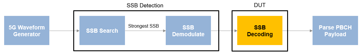
SSB detection performs a primary synchronization sequence (PSS) search, orthogonal frequency division multiplexing (OFDM) demodulation, and a secondary synchronization sequence (SSS) search. SSB detection has two modes of operation: search and demodulation. In search mode, the detection searches for SSBs and returns their parameters. In demodulation mode, the detection recovers a specified SSB, OFDM-demodulates its resource grid, and searches for the SSS within the appropriate resource elements. The details of SSB detection and demodulation are described in the NR HDL Cell Search example.
SSB decoding performs a demodulation reference signal (DMRS) search, channel estimation and phase equalization, and broadcast channel (BCH) decoding steps. The details of SSB decoding are described in the NR HDL MIB Recovery example.
5G waveform generator uses 5G Toolbox™ functions to generate a test waveform, which is then applied to the SSB detection in search mode. After the strongest SSB is determined, the test waveform is applied to the SSB detection in demodulation mode to recover a specified SSB resource grid and search for the SSS within the appropriate resource element.
After an SSB is detected and demodulated, it needs to be decoded to extract the MIB content. When SSB decoding has the demodulated grid, the SSB decoding module decodes the SSB and output the PBCH payload, which is then parsed to extract the MIB data.
File Structure
This example uses these files.
Simulink models
nrhdlSSBDetection.slx: This Simulink model uses thenrhdlSSBDetectionFR1Coremodel reference to simulate the behavior of the SSB detection part of the MIB recovery process.nrhdlSSBDetectionFR1Core.slx: This model reference implements the SSB detection algorithm.nrhdlSSBDecoding.slx: This Simulink model uses thenrhdlSSBDecodingCoremodel reference to simulate the behavior of the SSB decoding part of the MIB recovery process.nrhdlSSBDecodingCore.slx: This model reference implements the SSB decoding algorithm.
Simulink data dictionary
nrhdlReceiverData.sldd: This Simulink data dictionary contains bus objects that define the buses contained in the example models.
MATLAB code
generate5GWaveform.m: This function is a modified version of the Wireless HDL Toolbox™ 5G waveform generator, which is C code generation compatible.runSSBDetectionModelSearch.m: This script executes and verifies thenrhdlSSBDetectionmodel in search mode.runSSBDecodingModel.m: This script uses the MATLAB reference to implement the cell search algorithm and then runs thenrhdlSSBDecodingSimulink model. The script verifies the operation of the model using 5G Toolbox and the MATLAB reference code.nrsvdpiexamples: This namespace contains the MATLAB reference code and utility functions for verifying the implementation models.
Pregenerated HDL testbench components (available for Windows® only)
5GNRCellDecodeDPITB: This folder contains generated DPI components, HDL code of the decoding module, and the top-level testbench with associated build and simulation scripts.
Set Up for HDL Simulation
This section describes the workflow for generating the DPI component for each 5G functional component and HDL code for the SSB decoding component. The provided top-level testbench instantiates all of the generated components to validate the behavior of the HDL code that is generated from the SSB decoding block. To enable reuse of individual SystemVerilog DPI components and use a subset of the components in a testbench, generate SystemVerilog DPI for each 5G component individually.
The 5GNRCellDecodeDPITB folder contains all of the necessary generated components. if you do not want to regenerate these components, skip this section.
5G Waveform Generator
This function uses 5G Toolbox functions to generate a test waveform. The 5G waveform generator has three input arguments: ncellid, SNR, and frequencyOffset. When you use this waveform generator in a SystemVerilog testbench, you can test different scenarios by providing different values for SNR, frequencyOffset, and ncellid without changing the component code. For this example, use this command to generate the DPI component from the MATLAB function generate5GWaveform.
dpigen generate5GWaveform -args {0,0,0} -PortsDataType LogicVector
The -args {0,0,0} parameter indicates that three scalar inputs of type double. The -PortsDataType LogicVector parameter indicates generating a logic vector type interface for the port.
SSB Detection
This component is introduced in the nrhdlSSBDetection Simulink model and the top-level testbench uses this component for the SSB search and SSB demodulation. Use these commands to run a search mode simulation and verify the results in MATLAB.
clear all;
runSSBDetectionModelSearch;
Then use this command to generate a DPI component for the Simulink subsystem nrhdlSSBDetection/SSB Detection.
slbuild('nrhdlSSBDetection/SSB Detection');
Choose Strongest PSS
This component is introduced in the nrhdlSSBDetection Simulink model and the top-level testbench uses this component to determine the strongest PSS from the PSSs detected by the SSB search. Use this command to generate a DPI component for the Simulink subsystem nrhdlSSBDetection/chooseStrongestPSS.
slbuild('nrhdlSSBDetection/chooseStrongestPSS');
SSB Decoding
This component is introduced in the nrhdlSSBDecoding Simulink model and is the DUT in this example. Use these commands to run an SSB decoding simulation in MATLAB.
clear all;
runSSBDecodingModel;
Then, use this command to generate HDL code from this component.
makehdl('nrhdlSSBDecoding/SSB Decoding','TargetLanguage','Verilog');
Parse PBCH Payload
This component is introduced in the nrhdlSSBDecoding Simulink model and the top-level testbench uses this component to parse the PBCH payload to obtain the MIB information. Use this command to generate the DPI component for the Simulink subsystem nrhdlSSBDecoding/parsePBCHPayload.
slbuild('nrhdlSSBDecoding/parsePBCHPayload');
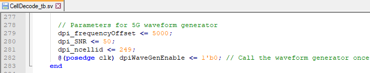
The 5GNRCellDecodeDPITB folder contains a top-level testbench, CellDecode_tb.sv, to simulate the entire process described in the MIB Recovery Process section. In this example, the ncellid parameter is set to 249, the SNR parameter is set to 50, and the frequencyOffset parameter is set to 5000. You can modify the values of these parameters to test the design in different scenarios.
Run Testbench
Add the QuestaSim simulator to the MATLAB system path, and then navigate to the 5GNRCellDecodeDPITB folder. To compile and simulate the DUT in QuestaSim, enter these commands at the MATLAB prompt.
!vsim < compile_dut.do
!vsim < sim_5G_waveform.do
Observe the following simulation results:
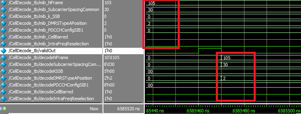
In this figure of a waveform, signal names that start with "mib" carry MIB information from the waveform generator, and signal names that start with "decode" carry MIB information from the decode process. The waveform shows that the decoded MIB information matches the MIB information from the waveform generator.
Using this approach, you can dynamically react to the status of each 5G functional component to save simulation time compared to a vector-based testbench.
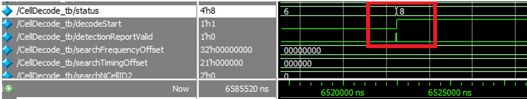
In this figure of a waveform, the value of the detection status changes from 6 to 8, indicating that the demodulation operation is complete. The SSS is found, and a demodulated resource grid is returned. In this case, you can start the SSB decoding process instead of waiting for SSB demodulation to finish processing the input vectors if you are using a vector-based HDL testbench.
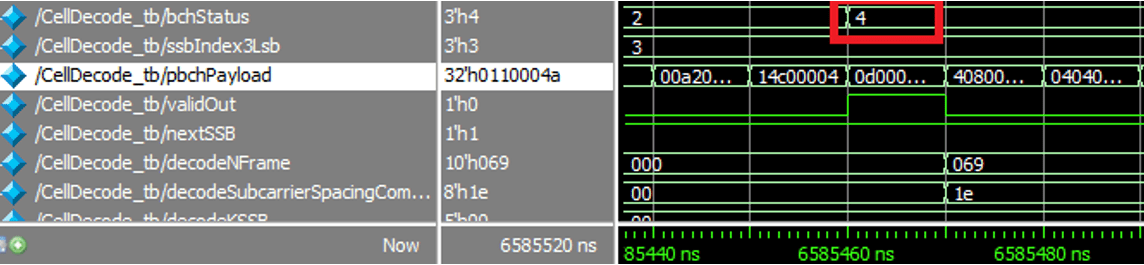
In this figure of a waveform, the value of the decoding status changes from 2 to 4, indicating that the MIB is detected. In this case, you can stop the simulation rather than finish processing the grid resource data. In contrast, the vector-based testbench approach requires simulation for a fixed amount of time before analyzing the results.
Reuse DPI Component
You can reuse the generated 5G function DPI components in a customized testbench.
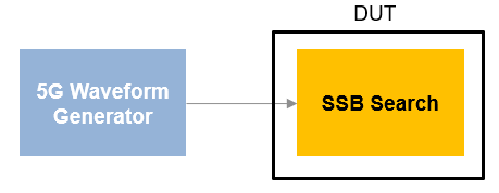
Use these components to test a subset of the MIB recover process. For example, reuse the 5G waveform generator to validate the behavior of an SSB search module.
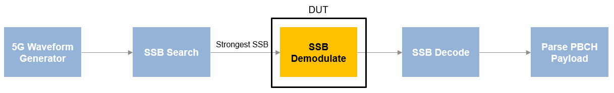
Use these components to test different 5G function components in the MIB recovery process. For example, when you are validating the behavior of SSB demodulation in the MIB recovery process, you can reuse the 5G waveform generator, SSB search and parse PBCH payload DPI components, and generate a DPI component from SSB decoding. Instantiate these components in your top-level testbench to validate the behavior of the SSB demodulate module.
Conclusion
This example shows how to use a standalone testbench with DPI components to validate the SSB decoding module of an MIB recovery process. The HDL Verifier™ generated DPI components support tunable parameters, which enable customization of the 5G test waveform from the top-level testbench. You can reuse each generated DPI component in other custom HDL testbenches. You can use this workflow for verifying the HDL IP in your wireless application.