NR HDL Cell Search
This example shows the design of a 5G NR cell search subsystem optimized for HDL code generation and hardware implementation.
Introduction
The Simulink® model described in this example is an HDL-optimized implementation of a synchronization signal block (SSB) detector for 5G NR frequency range 1 (FR1). This example is one of a related set, for more information see NR HDL Reference Applications Overview.
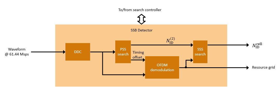
A block diagram of the SSB detector is shown in the figure. The detector performs all of the high-speed signal processing tasks associated with the cell search algorithm therefore is well suited for FPGA or ASIC implementation. The SSB detector searches for SSBs in time at a given frequency offset and subcarrier spacing. It is designed to be used as part of a larger system that implements carrier frequency offset recovery and subcarrier spacing detection. A controller must be used co-ordinate the overall cell search as shown in the 5G NR MIB Recovery Using Analog Devices AD9361/AD9364 (SoC Blockset) example.
The SSB detector performs primary synchronization sequence (PSS) search, orthogonal frequency division multiplexing (OFDM) demodulation, and secondary synchronization sequence (SSS) search. It also includes a digital down converter (DDC) for correcting frequency offsets in the received signal. The SSB detector has two modes of operation, search and demodulation, which are demonstrated in this example. In search mode, the detector searches for SSBs and returns their parameters. In demodulation mode, the detector recovers a specified SSB OFDM-demodulates its resource grid and searches for SSS within the appropriate resource elements.
File Structure
The example uses these files.
Simulink models
nrhdlSSBDetection.slx: This Simulink model uses the simulates the behavior of SSB detection.nrhdlSSBDetectionFR1Core.slx: This model implements the SSB detection algorithm.nrhdlDDCFR1Core.slx: This model implements a DDC to create sample streams for SIB1 and SSBs.
Simulink data dictionary
nrhdlReceiverData.sldd: This Simulink data dictionary contains bus objects that define the buses contained in the example models.
MATLAB code
runNRSSBDetectionModelSearch.m: Script for running and verifying thenrhdlSSBDetectionmodel in search mode.runNRSSBDetectionModelDemod.m: Script for running and verifying thenrhdlSSBDetectionmodel in demodulation mode.nrhdlexamples: Namespace containing the MATLAB reference code and utility functions for verifying the implementation models.
NR HDL Cell Search Model
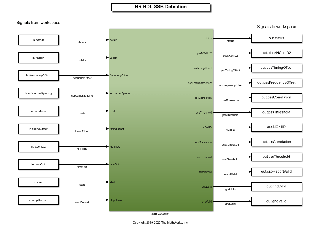
This figure shows the nrhdlSSBDetection model. The top level of the model reads signals from the MATLAB base workspace, passes them to the SSB Detection subsystem, and writes the outputs back to the workspace. Use the runNRSSBDetectionModelSearch and runNRSSBDetectionModelDemod scripts to run the model and post-process the outputs.
SSB Detection Subsystem
The SSB Detection subsystem references the nrhdlDDCFR1Core and nrhdlSSBDetectionFR1Core models. The DDC performs frequency offset correction and decimation, and the SSB Detector searches for and demodulates SSBs. The algorithms of the model references are described in the next sections. The output of the DDC is the input to the SSB Detection algorithm.

Inputs
dataIn: 14-bit signed complex-valued signal, sampled at 61.44 Msps.
validIn: 1-bit control signal to validate dataIn.
frequencyOffset: 32-bit signed value specifying the frequency offset to be corrected. This signal is connected to an NCO with a 32-bit accumulator. Use this equation to convert the value to Hz: frequencyOffset_Hz = frequencyOffset * 61.44e6 / 2^32.
subcarrierSpacing: 2-bit unsigned value specifying the subcarrier spacing. Set this signal to 0 to select 15kHz, or 1 to select 30kHz.
mode: 2-bit unsigned value specifying the operation mode. Set this signal to 0 for search mode, 1 for single demodulation mode and 2 for repeat demodulation mode.
timingOffset: 21-bit unsigned value specifying the timing offset of the start of the SSB to be demodulated. Specify the timing offset in samples at 61.44 Msps, from 0 to 1228799. This parameter applies only for demodulation mode.
NCellID2: 2-bit unsigned value specifying the PSS (0, 1, or 2) of the SSB to be demodulated. This parameter applies only for demodulation mode.
timeOut: 3-bit unsigned value specifying the time out count for repeat demodulation mode. When the SSB detector fails to detect timeOut + 1 SSBs in a row it terminates.
stopDemod: 1-bit control signal that stops the repeat demodulation mode operation when asserted.
start: 1-bit control signal used to start a search or demodulation operation. To start an operation, set frequencyOffset, subcarrierSpacing, mode, timingOffset, and NCellID2 to the desired values and set start to 1 (true) for one or more cycles. If an operation is already in progress, that operation is canceled when start is set to 1 (true). The new operation begins when start is returned to 0 (false).
Outputs
status: 4-bit unsigned value that indicates the progress of the current operation. See the next section for the possible values of this signal.
pssNCellID2: 2-bit unsigned value that is the PSS (0, 1 or 2) of the detected SSB.
pssTimingOffset: 21-bit unsigned value that is the timing offset of the detected SSB. The timing offset is in samples at 61.44 Msp from 0 to 1228799.
pssFrequencyOffset: 32-bit signed value that is the frequency offset of the detected SSB. This signal has the same units as the frequencyOffset input.
pssCorrelation: 32-bit unsigned value that is the strength of the PSS correlation.
pssThreshold: 32-bit unsigned value that is the threshold value when PSS was detected.
NCellID: 10-bit unsigned value that is the cell ID of the demodulated SSB. This value is returned only in demodulation mode.
sssCorrelation: 32-bit unsigned value that is the SSS correlation strength. This signal is returned only in demodulation mode.
sssThreshold: 32-bit unsigned value that is the SSS threshold. This value is returned only in demodulation mode.
reportValid: 1-bit control signal. In search mode, this signal validates pssNCellID2, pssTimingOffset, pssFrequencyOffset, pssCorrelation, and pssThreshold for each PSS that is detected. In demodulation mode, this signal also validates NCellID, sssCorrelation, and sssThreshold. In demodulation mode, sssCorrelation and sssThreshold are only valid if the specified SSB was found using its PSS, and NCellID is only valid if the SSS was detected.
gridData: 16-bit signed complex-values that are the resource grid data. The receiver returns all four symbols of the SSB resource grid. Values are returned one resource element at a time. The resource grid is only returned in demodulation mode.
gridValid: 1-bit control signal that validates the gridData output. Data is only returned if the specified SSB was found using its PSS. This signal is returned only in demodulation mode.
diagnostics: Bus containing diagnostic signals.
Status Signal States
0: Idle -- Initial state. Waiting for first start pulse.1: Search mode -- Searching for PSS.2: Search mode -- Operation complete, no PSS found.3: Search mode -- Operation complete, found one or more PSSs.4: Demodulation mode -- Waiting for specified PSS timing offset.5: Demodulation mode -- Operation complete, PSS not found.6: Demodulation mode -- Found specified PSS. Demodulating the resource grid and looking for SSS.7: Demodulation mode -- Operation complete, no SSS found. Returned demodulated resource grid.8: Demodulation mode -- Operation complete, found SSS. Returned demodulated resource grid.
DDC Model
This diagram shows the top level of the nrhdlDDCFR1Core model. The input signal (dataIn) is 16-bit signed complex-valued data sampled at 61.44 Msps. The DDC performs two operations for SSBs. First, the Input Scaling subsystem scales the input by a factor of 0.875, providing headroom for the subsequent processing stages. Second, the SSB DDC subsystem applies the given SSB frequency offset to the data stream, and then filters and decimates the samples by eight using a chain of halfband filters. The ssbData output is sampled at 7.68 Msps and is used for SSB detection. This sample rate is the minimum bandwidth required to compute a power of 2 FFT for the SCS 30 SSB. The Grid DDC subsystem applies the given grid frequency offset, and then filters and decimates the samples by two. The gridData output is sampled at 30.72 Msps. The Grid DDC, and the gridData output are used in the NR HDL SIB1 Recovery example, where the DDC drives both the SSB and SIB1 processing steps.

SSB Detection Model
This diagram shows the top level of the nrhdlSSBDetectionFR1Core model. The model performs SSB detection and demodulation. Its internal sampling rate varies depending on the subcarrier spacing (SCS). The model uses 7.68 Msps for 30kHz SCS and 3.84 Msps for 15kHz SCS. The Subcarrier Spacing Selection subsystem on the left is responsible for changing the sampling rate. The rate can change only when a new operation is triggered by the startProcessing input.
The receiver has an internal timing reference system that keeps track of time by using counters at key points in the datapath. Time is measured in samples at 61.44 Msps modulo 1228800. Therefore the timing reference wraps around every 20ms - the assumed SSB periodicity for cell search as defined by the 5G NR standard. Since the actual sampling rate is either 7.84 Msps or 3.84 Msps, the timing reference counters increment by either 8 or 16, respectively, for each sample. The timing reference is relative to the first valid sample at the input and runs continuously. When a new operation is triggered by the start input, the timing reference is not restarted. Instead, the start time is recorded at the input timing reference. The other timing references wait until reaching the start time before changing their increment, when a new subcarrier spacing and corresponding sampling rate applies. This architecture enables the receiver to keep track of time consistently, even when a sampling rate change occurs. Due to hardware latency, the other timing references lag behind the input timing reference. The timing update process relies on this latency.
The nrhdlSSBDetectionFR1Core model contains these main subsystems.
Subcarrier Spacing Selection: Converts the input to two synchronized sample streams, one at 7.68 Msps and one at 3.84 Msps, and selects which stream to pass to subsequent processing stages according to the subcarrier spacing.
SSB Search: Performs PSS correlation to search for SSBs.
SSB Demod: Performs OFDM demodulation and SSS correlation.
Report Creation: Aligns all of the parameters corresponding to one SSB detection, so that they are all valid at the same time.
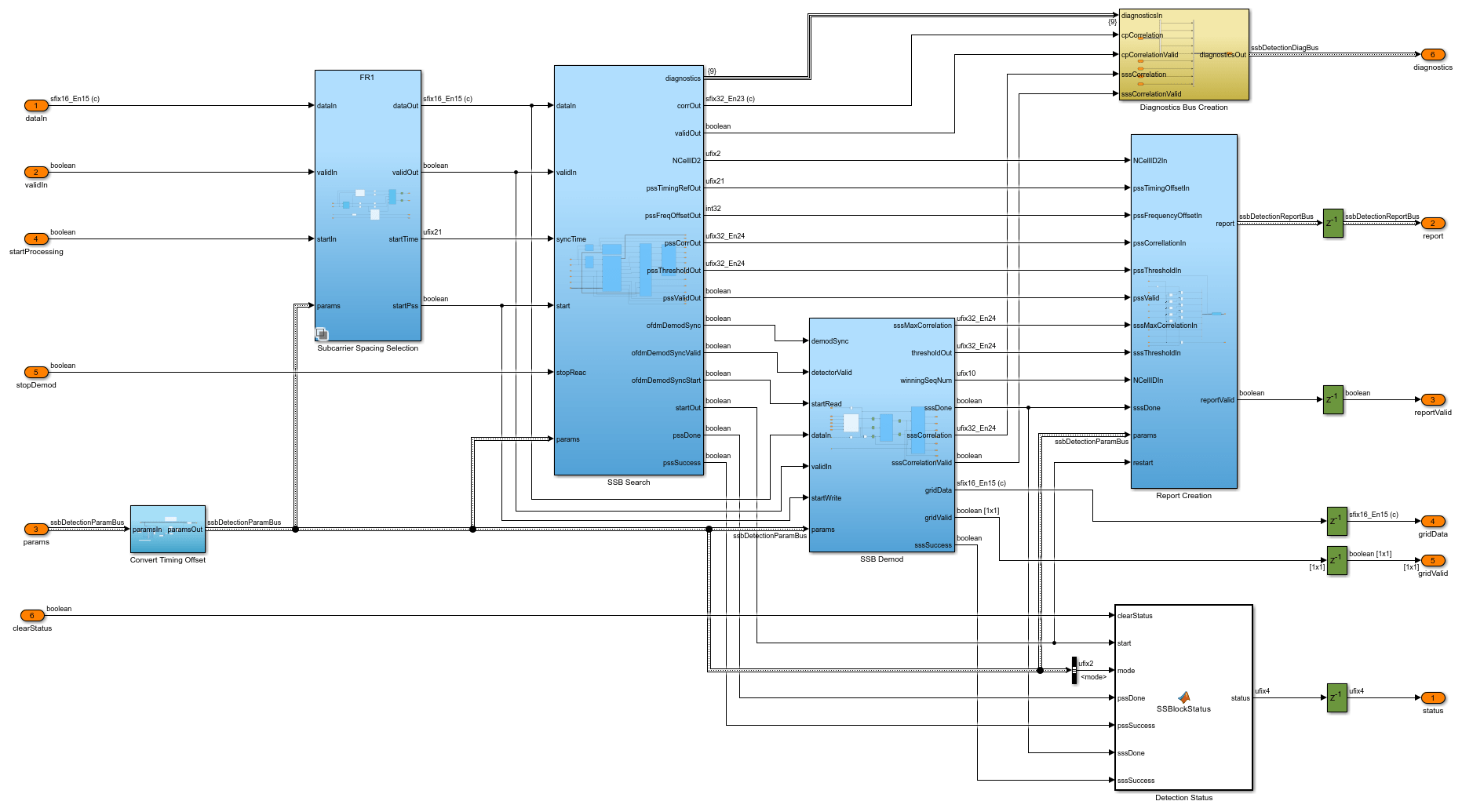
SSB Search subsystem
PSS Detection: Searches for PSS symbols in the received signal.
Cyclic Prefix Correlation: Computes cyclic prefix (CP) correlation values. Each result is averaged across the last four OFDM symbols.
CP Correlation to Frequency: Converts CP correlation values to fine frequency offset estimates.
PSS and CP Alignment: Matches a CP-based frequency estimate with each PSS symbol detection instance. This alignment is necessary because the frequency estimate for a given PSS detection instance is available only at the end of the corresponding SSB.
PSS Info Serialization: If PSS is detected on more than one PSS correlator output at the same timing offset, this block serializes the results so that they are returned from the detector one at a time.
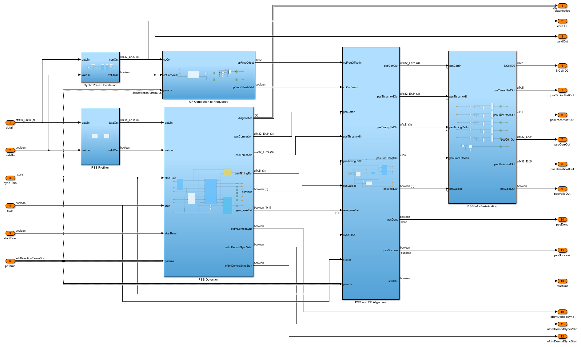
SSB Demod subsystem
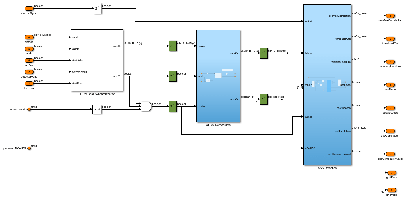
OFDM Data Synchronization: Synchronizes the OFDM demodulator input with the output of the PSS detector. This synchronization enables the PSS detector to trigger the OFDM demodulation process at the correct time. The synchronized data is one OFDM symbol behind the PSS correlator as the peak detection occurs at the end of the first OFDM symbol to be demodulated.
OFDM Demodulation: OFDM-demodulates `the four symbols of the specified SSB.
SSS Detection: Extracts the SSS resource elements from the OFDM demodulator output and correlates them with all 336 possible sequences to determine the cell ID.
Cell Search Operations
The design operates in one of two modes - search or demodulation. Performing these operations sequentially allows a controller to perform a full cell search.
1. Search Mode
In search mode, the SSB detector searches for SSBs at the specified subcarrier spacing and frequency offset by correlating against each PSS sequence. The operation outputs a list of the detected SSBs, defined by a timing offset and PSS sequence ID. The correlation metrics and frequency offset for each SSB are reported. After a successful search operation the SSB detector automatically tracks the strongest detected PSS to maintain timing lock until a demodulation operation begins, and records the total timing slip. The input timing offset supplied for the demodulation operation is combined with this total timing slip to calculate the final timing occasion. This calculation improves the robustness of the design in the presence of a sample rate offset, or a delay between completion of a search step and the start of a demodulation step.
2. Demodulation Mode
In demodulation mode, the detector demodulates the SSB specified by the timingOffset and NCellID2 inputs. This involves searching for its PSS, OFDM-demodulating the resource grid, and searching for the SSS within the appropriate resource elements. Demodulation mode requires the results of a successful search operation. The specified SSB is selected from the list of SSBs detected.
There are two demodulation modes: single demodulation mode and repeat demodulation mode. In single demodulation mode, the operation terminates after one demodulation attempt. In repeat demodulation mode, the operation is performed every 20ms, the assumed periodicity of SSB transmission for cell search purposes. A set of results are reported after each attempt. The repeated demodulation enables the monitoring and measurement of a single SSB over multiple transmission occasions. The repeat mode runs until the timeout count is reached or the stop demodulation input is asserted. The timeout count increments when the SSB timing offset is reached and no PSS correlation is detected, and resets to zero when a correlation is detected within a timing window. In the presence of a sample rate offset the SSB timing offset drifts between each demodulation attempt. The repeat demodulation operation tracks this drift and shifts the expected timing offset in integer increments automatically. The drift offset is in units of whole samples measured at the SSB rate for the selected SCS. The tracking operates on a window of five samples centered around the expected timing occasion. If the timing slip over the 20ms period is greater than two samples at the SSB rate then the peak will move outside the window and the tracking may fail. Additionally, the frequency offset measured on each repetition is applied to the DDC to correct any drift in the frequency of the SSB. These corrections allow the receiver to track and repeatedly demodulate an SSB over an extended period of time.
Simulation Setup
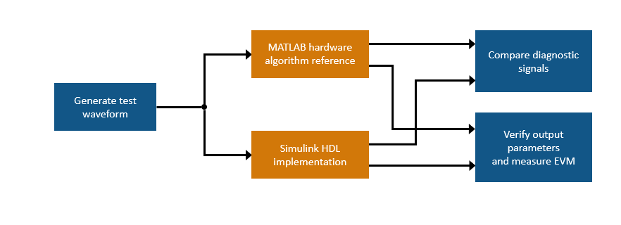
The block diagram shows the simulation setup of this example, which is implemented in the runNRSSBDetectionModelSearch and runNRSSBDetectionModelDemod scripts. 5G Toolbox™ functions are used to generate a test waveform which is applied to the MATLAB and Simulink implementations of the SSB detector in search mode and then in demodulation mode. Key diagnostic signals from each detector are compared in terms of their relative mean-squared error (MSE) and the final outputs are compared. Finally, the resource grid output of the Simulink model is decoded to show that the MIB contents are as expected.
The Test bench options section of the runNRSSBDetectionModelSearch script includes these variables to configure the simulation:
simulationCase: specifies the configuration of the generated waveform. The table shows the set of simulation cases.
    Simulation Case    SSB Pattern    Subcarrier Spacing Common    PDCCH Config SIB1    SNR dB    Strongest SSB index    Lmax
    _______________    ___________    _________________________    _________________    ______    ___________________    ____

      "SimCase 1"       "Case C"                 30                       164             50               4              8
      "SimCase 2"       "Case B"                 15                       100              6               3              4
      "SimCase 3"       "Case A"                 30                         4             20               2              8
      "SimCase 4"       "Case A"                 15                        84              7               0              4
numSubFrames: specifies the number of 1 ms subframes generated as input stimulus.
repeatDemodEn: specifies single or repeat demodulation mode.
sampleSlip: specifies the sample slip per 20ms applied to the generated waveform.
Search Mode Simulation
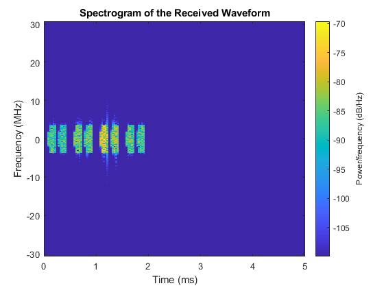
Use the runNRSSBDetectionModelSearch script to run a search mode simulation and verify the results. The script displays its progress in the MATLAB command window. Tables show the parameters of each SSB detected by MATLAB and Simulink. The final table shows the relative MSE between MATLAB and Simulink for each correlator output and for the detection threshold. Plots are generated showing (i) the combined resource grid of all eight SSBs in the transmitted waveform and (ii) the PSS correlation outputs and threshold. The results show that the MATLAB and Simulink implementations match very closely. The small differences between the two implementations are due to quantization errors. These errors occur because the MATLAB reference uses floating-point data types, and the Simulink model uses fixed-point data types.
runNRSSBDetectionModelSearch;
Generating test waveform.
Selected Simulation case:

    Simulation Case    SSB Pattern    Subcarrier Spacing Common    PDCCH Config SIB1    SNR dB    Strongest SSB index    Lmax
    _______________    ___________    _________________________    _________________    ______    ___________________    ____

      "SimCase 1"       "Case C"                 30                       164             50               4              8

Searching for SSBs using the MATLAB reference.
Searching for SSBs using the Simulink model.
Running nrhdlSSBDetection.slx
### Searching for referenced models in model 'nrhdlSSBDetection'.
### Total of 2 models to build.
### Starting serial model build.
### Model reference simulation target for nrhdlDDCFR1Core is up to date.
### Model reference simulation target for nrhdlSSBDetectionFR1Core is up to date.

Build Summary

0 of 2 models built (2 models already up to date)
Build duration: 0h 0m 1.0317s
..........

SSBs found by MATLAB reference:
    NCellID2    timingOffset    pssCorrelation    pssEnergy    frequencyOffset
    ________    ____________    ______________    _________    _______________

       0               4440         1.8473         2.0636           5075
       0              17592         1.4711         1.6411           4990
       0              35160         3.7065         4.1329           5013
       0              48312         2.9127         3.2564           5038
       0              65880         11.656         13.013           4949
       0              79032         4.6311         5.1659           4993
       0              96600         2.3301         2.5946           5008
       0         1.0975e+05         1.6463         1.8361           4987

SSBs found by Simulink model:
    NCellID2    timingOffset    pssCorrelation    pssEnergy    frequencyOffset
    ________    ____________    ______________    _________    _______________

       0               4440         1.8481         2.0641           5075
       0              17592         1.4716         1.6415           4990
       0              35160         3.7067         4.1338           5013
       0              48312         2.9131         3.2571           5038
       0              65880         11.657         13.015           4949
       0              79032         4.6324         5.1668           4993
       0              96600         2.3306         2.5952           5008
       0         1.0975e+05         1.6465         1.8365           4987


Relative mean-squared error between MATLAB and Simulink in search mode:

            name             relativeMSEdB
    _____________________    _____________

    {'PSS correlation 0'}       -71.833
    {'PSS correlation 1'}       -63.524
    {'PSS correlation 2'}       -63.245
    {'PSS threshold'    }       -77.851

Use the Simulink Logic Analyzer to view the inputs and outputs to the SSB Detection subsystem. The detector looks for PSS symbols within a 20 ms time window, which begins after a pulse on the start input triggers the search operation. If no PSS symbols are found after 20 ms, the detector sets the status output to 2 - indicating that the search has failed. In this example, the detector finds all eight SSBs. The status output is set to 1 during the search, and a report is returned for each SSB by asserting the reportValid signal. The simulation only runs for 5 ms however if it is extended to run for more than 20 ms, then the status output is eventually set to 3 - indicating that the search has succeeded.

Demodulation Mode Simulation
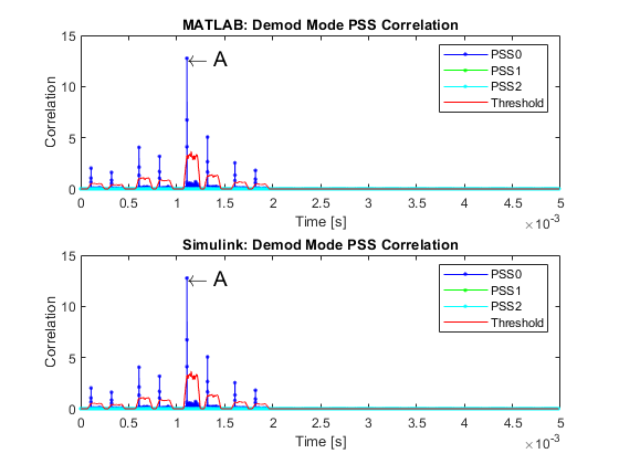
After running runNRSSBDetectionModelSearch, use the runNRSSBDetectionModelDemod script to run a single demodulation mode simulation and verify the results. The script displays its progress in the MATLAB command window. SSB reports from MATLAB and Simulink show that both detectors returned similar parameters and determined the cell ID correctly as 249. Relative MSE measurements indicate that the MATLAB and Simulink implementations match very closely. As a final verification step, the script decodes the broadcast channel (BCH) from the Simulink resource grid output. The CRC check passes and the master information block (MIB) contents match the transmission. Plots are generated which show the PSS and SSS correlation results, and the resource grid output. The PSS correlation levels are stronger in the demodulation mode simulation than in search mode simulation because the frequency offset is corrected.
runNRSSBDetectionModelDemod;
Choosing the strongest PSS from the previous search and computing its frequency offset.
       Strongest PSS index (1 based): 5
    Frequency offset (coarse + fine): 4.949 kHz

Demodulating the strongest SSBs using the MATLAB reference.
Demodulating the strongest SSBs using the Simulink model.
Running nrhdlSSBDetection.slx
### Searching for referenced models in model 'nrhdlSSBDetection'.
### Total of 2 models to build.
### Starting serial model build.
### Model reference simulation target for nrhdlDDCFR1Core is up to date.
### Model reference simulation target for nrhdlSSBDetectionFR1Core is up to date.

Build Summary

0 of 2 models built (2 models already up to date)
Build duration: 0h 0m 0.27292s
..........

Relative mean-squared error between MATLAB and Simulink in demod mode:

            name             relativeMSEdB
    _____________________    _____________

    {'PSS correlation 0'}       -69.767
    {'PSS threshold'    }        -69.74
    {'SSS correlation'  }       -70.744
    {'Rx resource grid' }       -70.257

------------- Displaying Results for SSB Demod A -------------

SSB demodulated at: 1.0723 ms

SS block report: from MATLAB
           NCellID2: 0
       timingOffset: 65880
     pssCorrelation: 12.7611
          pssEnergy: 12.9944
           NCellID1: 83
     sssCorrelation: 12.9237
          sssEnergy: 13.0894
            NCellID: 249
    frequencyOffset: 0

SS block report: from Simulink
           NCellID2: 0
       timingOffset: 65880
     pssCorrelation: 12.7644
          pssEnergy: 12.9983
           NCellID1: 83
     sssCorrelation: 12.9256
          sssEnergy: 13.0935
            NCellID: 249
    frequencyOffset: 0

Decoding BCH from Simulink resource grid output:

 BCH CRC: 0

 Decoded (Rx) MIB
                     NFrame: 0
    SubcarrierSpacingCommon: 30
                      k_SSB: 0
          DMRSTypeAPosition: 3
            PDCCHConfigSIB1: 164
                 CellBarred: 0
       IntraFreqReselection: 0

 Expected (Tx) MIB
                     NFrame: 0
    SubcarrierSpacingCommon: 30
                      k_SSB: 0
          DMRSTypeAPosition: 3
            PDCCHConfigSIB1: 164
                 CellBarred: 0
       IntraFreqReselection: 0
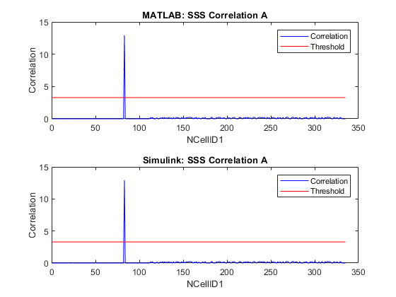

Use the Simulink Logic Analyzer to view the detector output as it progresses through these steps.
The detector sets the status output to
4while it waits for the specified timing offset and searches for the specified PSS.PSS is found. The detector sets the status output to
6- the detector is now searching for the SSS within the resource grid. The four demodulated OFDM symbols are output, indicated by asserting gridValid.After the SSS is determined, the detector asserts reportValid to indicate that all of the PSS and SSS parameters, including NCellID, are valid. The status output changes to
8, to indicate that the operation is complete and SSS and cell ID are ready.
If the PSS is not found at the specified timing offset, the detector sets the status output to 5 and stops searching. If the detector is unable to determine the SSS, then it sets the status output to 7. In this example, the detector recovers the specified SSB - the SSB with the strongest PSS from the initial search.

Further Exploration
This section shows how to run a simulation in repeat demodulation mode by modifying the options described in the Simulation Setup section.
Increase the length of the generated waveform to contain a second SSB transmission. Generating a waveform with 25 subframes provides enough input data to perform two SSB demods in repeat mode. Increase the value further to perform more demodulations.
numSubFrames = 25;
Enable the repeat demodulation mode to perform multiple SSB demodulations.
repeatDemodEn = 1;
Apply a sample rate offset to the waveform. The sample slip is specified in units of input samples per 20ms. The design is robust to sample slips of up to two samples per 20ms at the SSB rate. The ratio between the SSB rate and the input rate is 16 for SCS 15, and 8 for SCS 30. Therefore, the sample slip can be -32 to 32 for SCS 15 and -16 to 16 for SCS 30.
sampleSlip = 8;
Run the runNRSSBDetectionModelSearch followed by the runNRSSBDetectionModelDemod scripts to perform the simulation.
With this input configuration the receiver demodulates two SSBs in demodulation mode. The PSS correlation plot shows the peaks of both SSB demodulation occasions, labelled A and B. Results are displayed for both demodulations in the Command Window.
HDL Code Generation and Implementation Results
To generate the HDL code for this example, you must have an HDL Coder™ license. Use the makehdl and makehdltb commands to generate HDL code and an HDL test bench for the nrhdlSSBDetection/SSB Detection subsystem. The resulting HDL code was synthesized for a Xilinx® Zynq®-7000 ZC706 evaluation board. The table shows the post place and route resource utilization results. The design meets timing with a clock frequency of 230 MHz.
       Resource        Usage
    _______________    _____

    Slice Registers    34819
    Slice LUTs         20861
    RAMB18                12
    RAMB36                 0
    DSP48                209