measureAntennaPhase
Syntax
Description
[___] = measureAntennaPhase(
specifies options using one or more name-value arguments in addition to the input arguments
in the previous syntaxes. For example, analyzer,direction,Name=Value)Antennas={["RF0:RX2","RF1:RX2"]
["RF0:RX2","RF1:RX2"]} specifies four antennas across two radios for phase
analysis.
[___,
also plots the measured mean spectrum magnitude versus phase offset for all antennas under
test and returns the handles to the plots in the figures] = measureAntennaPhase(___,PlotResult=true)figures output
argument.
Examples
This example shows how to measure relative phase offsets between transmit antennas on a single radio using the basebandPhaseAnalyzer object. The example uses a second USRP radio to capture the monitor signal.
Create Radio Objects
Create a radio object for each radio, specifying a radio setup configuration previously saved using the Radio Setup wizard.
radio = radioConfigurations("MyRadio"); radio2 = radioConfigurations("MyRadio2");
Specify Antennas
Define the antennas under test and the monitor antenna.
antennasUnderTest = ["RF0:TX/RX" "RF1:TX/RX"]; monitorAntenna = "RF1:RX2";
Configure Baseband Transceivers
Create and configure a basebandTransceiver application object for each radio. Use the same RF properties on both radios. Specify all RF properties using the PropertyName=Value syntax and preload the FPGA image.
transmitGain = 20; captureGain = 30; bbtrx = basebandTransceiver(radio, ... Preload=true, ... TransmitAntennas=antennasUnderTest, ... TransmitRadioGain=transmitGain); bbtrx2 = basebandTransceiver(radio2, ... Preload=true, ... CaptureAntennas=monitorAntenna, ... CaptureRadioGain=captureGain);
Synchronize Radio Time
Synchronize both radios to a common time using the next PPS signal.
tLastPPS = getTimeLastPPS(radio); while tLastPPS == getTimeLastPPS(radio) pause(0.1) end setTimeNextPPS(radio,0); setTimeNextPPS(radio2,0);
Verify that the radio time is synchronized.
pause(1.1) tLastPPS1 = getTimeLastPPS(radio); tLastPPS2 = getTimeLastPPS(radio2); isequal(tLastPPS1,tLastPPS2)
ans = logical
1
If the radio time synchronization is unsuccessful, rerun this section.
Estimate Relative Phase Offsets
Create a phase analyzer object.
bbpa = basebandPhaseAnalyzer(RadioApplication=bbtrx, ...
MonitorApplication=bbtrx2,MonitorAntenna=monitorAntenna);Estimate the relative phase offsets of the specified transmit antennas and plot the measurement results.
[phase,results] = measureAntennaPhase(bbpa,"transmit")phase = 1×1 cell array
{[0 -60.0394]}
results = 1×1 cell array
{72×2 double}
This example shows how to measure relative phase offsets between capture antennas on a single radio using the basebandPhaseAnalyzer object. The example uses a second USRP radio to transmit the stimulus signal.
Create Radio Objects
Create a radio object for each radio, specifying a radio setup configuration previously saved using the Radio Setup wizard.
radio = radioConfigurations("MyRadio"); radio2 = radioConfigurations("MyRadio2");
Specify Antennas
Define the stimulus antenna and the antennas under test.
antennasUnderTest = ["RF0:RX2" "RF1:RX2"]; stimulusAntenna = "RF1:TX/RX";
Configure Baseband Transceivers
Create and configure basebandTransceiver application objects for each radio. Use the same RF properties on both radios. Specify all RF properties using the PropertyName=Value syntax and preload the FPGA image.
transmitGain = 20; captureGain = 30; bbtrx = basebandTransceiver(radio, ... Preload=true, ... CaptureAntennas=antennasUnderTest, ... CaptureRadioGain=captureGain); bbtrx2 = basebandTransceiver(radio2, ... Preload=true, ... TransmitAntennas=stimulusAntenna, ... TransmitRadioGain=transmitGain);
Synchronize Radio Time
Synchronize both radios to a common time using the next PPS signal.
tLastPPS = getTimeLastPPS(radio); while tLastPPS == getTimeLastPPS(radio) pause(0.1) end setTimeNextPPS(radio,0); setTimeNextPPS(radio2,0);
Verify that the radio time is synchronized.
pause(1.1) tLastPPS1 = getTimeLastPPS(radio); tLastPPS2 = getTimeLastPPS(radio2); isequal(tLastPPS1,tLastPPS2)
ans = logical
1
If the radio time synchronization is unsuccessful, rerun this section.
Estimate Relative Phase Offsets
Create a phase analyzer object.
bbpa = basebandPhaseAnalyzer(RadioApplication=bbtrx, ...
StimulusApplication=bbtrx2,StimulusAntenna=stimulusAntenna);Estimate the relative phase offsets of the specified capture antennas and plot the measurement results.
phase = measureAntennaPhase(bbpa,"capture")phase = 1×1 cell array
{[0 171.6380]}
This example shows how to measure relative phase offsets between capture antennas using the basebandPhaseAnalyzer object. The example uses a USRP N321 and USRP N320 radio with LO sharing configured.
Create Radio Objects
Create a radio object for each radio, specifying a radio setup configuration previously saved using the Radio Setup wizard.
radio1 = radioConfigurations("MyN321"); radio2 = radioConfigurations("MyN320");
Specify Antennas
Define the stimulus antenna and the antennas under test.
stimulusAntenna = "RF1:TX/RX"; antennasUnderTest_radio1 = "RF0:RX2"; antennasUnderTest_radio2 = ["RF0:RX2" "RF1:RX2"];
Configure Baseband Transceivers
Create and configure basebandTransceiver application objects for each radio. Use the same RF properties on both radios. Specify all RF properties using the PropertyName=Value syntax and preload the FPGA image.
transmitGain = 20; captureGain = 30; bbtrx1 = basebandTransceiver(radio1, ... Preload=true, ... CaptureAntennas=antennasUnderTest_radio1, ... CaptureRadioGain=captureGain, ... TransmitAntennas=stimulusAntenna, ... TransmitRadioGain=transmitGain); bbtrx2 = basebandTransceiver(radio2, ... Preload=true, ... CaptureAntennas=antennasUnderTest_radio2, ... CaptureRadioGain=captureGain);
Synchronize Radio Time
Synchronize both radios to a common time using the next PPS signal.
tLastPPS = getTimeLastPPS(radio1); while tLastPPS == getTimeLastPPS(radio1) pause(0.1) end setTimeNextPPS(radio1,0); setTimeNextPPS(radio2,0);
Verify that the radio time is synchronized.
pause(1.1) tLastPPS1 = getTimeLastPPS(radio1); tLastPPS2 = getTimeLastPPS(radio2); isequal(tLastPPS1,tLastPPS2)
ans = logical
1
If the radio time synchronization is unsuccessful, rerun this section.
Estimate Relative Phase Offsets
Create a phase analyzer object.
bbpa = basebandPhaseAnalyzer(RadioApplication={bbtrx1,bbtrx2}, ...
StimulusApplication=bbtrx1,StimulusAntenna=stimulusAntenna);Estimate the relative phase offsets of the specified capture antennas and plot the measurement results.
phase = measureAntennaPhase(bbpa,"capture",PlotResult=true, ... Antennas={antennasUnderTest_radio1 antennasUnderTest_radio2});
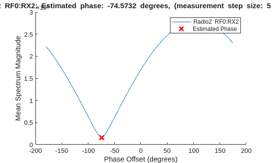
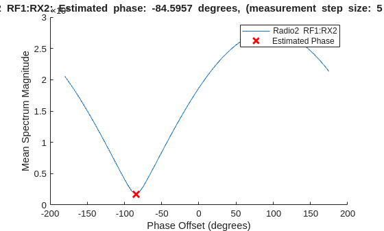

Display Results
Display the measured phase offsets in degrees.
disp("Measured phase estimates: ["+num2str(phase{1}(1))+" " + ... ""+num2str(phase{2}(1))+", "+num2str(phase{2}(2))+"]")
Measured phase estimates: [0 -74.5732, -84.5957]
Input Arguments
Phase analyzer object, specified as a basebandPhaseAnalyzer object.
Direction of phase measurement, specified as one of these options:
"transmit"— Estimate the relative phase offsets of transmit antennas by using a capture antenna as a monitor."capture"— Estimate the relative phase offsets of capture antennas by using a transmit antenna as a stimulus, or an external stimulus.
Data Types: string
Name-Value Arguments
Specify optional pairs of arguments as
Name1=Value1,...,NameN=ValueN, where Name is
the argument name and Value is the corresponding value.
Name-value arguments must appear after other arguments, but the order of the
pairs does not matter.
Example: {["RF0:RX2","RF1:RX2"] ["RF0:RX2","RF1:RX2"]} specifies four
capture antennas across two radios for relative phase offset measurement. Each string vector
corresponds to a radio specified in the RadioApplications property of the phase analyzer object analyzer.
Antennas under test, specified as {}, a string vector, or a
cell array of string vectors. Each element in the cell array corresponds to a radio
specified in the RadioApplications property of the phase analyzer object
analyzer.
If no antennas are specified, the function measures the relative phase offset of
all available transmit or capture antennas, depending on the specified direction.
Example: {["RF0:RX2","RF1:RX2"] ["RF0:RX2","RF1:RX2"]}
corresponds to two radios, each with two capture antennas under test.
Data Types: string
Initial phase estimates in degrees, specified as a numeric row vector or a cell
array of numeric row vectors where each row vector corresponds to a radio specified in
the RadioApplications property of the phase analyzer object
analyzer. The
length of each row vector corresponds to the number of antennas under test on the
corresponding radio.
Use this name-value argument to refine your measurements by providing estimates measured in a previous calibration and reducing the range and step size. The value of the first element in the row vector that corresponds to the first radio must be 0, since the other phase offsets are relative to the phase of the first antenna.
Example: {[0 127] [298 44]} corresponds to two radios, each with
two antennas under test.
Phase increment in degrees, specified as a numeric scalar. If the NumSteps
name-value argument is specified, the default value is
360/. Otherwise, the default value
is 5 degrees.NumSteps
Number of phase offset steps, specified as a numeric scalar. If the StepSize
name-value argument is specified, the default value is
360/. Otherwise, the default value
is StepSize72.
Option to plot measurement results, specified as false or
true.
The plot displays the measured mean spectrum magnitude versus phase offset for each antenna. The estimated phase offset is the minimum mean spectrum magnitude, which is refined using fractional peak estimation. Use the plot to visually inspect the results and confirm that you are satisfied with the resolution of the result.
Data Types: logical
Number of samples to capture per antenna, specified as an integer scalar greater
than 600. The default value is the sample rate of the radio divided by 250. To access
or set the sample rate of the radio, use the SampleRate of the corresponding
basebandTransceiver application object.
Specify a larger value to improve robustness to noise. Specify a smaller value if you encounter host transfer performance issues, especially when using direct host streaming with multiple antennas, for example, on a USRP™ X310 radio with TwinRX daughterboards.
The minimum value is 600 because the software discards the first 500 samples to remove non-steady-state effects.
Output Arguments
Estimated relative phase offsets in degrees, returned as a numeric row vector or a cell array of numeric row vectors.
If a single radio is specified in the
RadioApplicationsproperty of the phase analyzer objectanalyzer, the output is a numeric row vector with length equal to the number of antennas.If multiple radios are specified, the output is a cell array with the number of elements equal to the number of radios. Each element in the cell array is a numeric row vector of length equal to the number of antennas associated with that radio.
The antenna that corresponds to the first element in the first row vector is used as a reference. The relative phase offset returned for this antenna is 0. The other values are measured relative to the reference antenna using fractional peak estimation.
For more information about how the measurements are performed, see Capture Calibration and Transmit Calibration.
Note
In systems that are not phase coherent, the phase offset of each antenna will drift over time due to hardware and environmental factors. Rerun the function periodically or after you make changes to the hardware to maintain the accuracy of the phase calibration. For more information, see Phase-Synchronize Operations.
Example: [0 127 298 44] corresponds to one radio with four
antennas under test.
Example: {[0 127] [298 44]} corresponds to two radios, each with
two antennas under test.
Data Types: double
Measurement data used for estimation, returned as a numeric matrix or a cell array of numeric matrices.
If a single radio is specified in the
RadioApplicationsproperty of the phase analyzer objectanalyzer, the output is a numeric matrix.If multiple radios are specified, the output is a cell array with the number of elements equal to the number of radios.
Each matrix has dimensions equal to the number of phase offset steps used in the measurement by the number of antennas under test. Each column in the matrix corresponds to one antenna, and each row represents the mean spectrum magnitude measured at a specific phase offset.
These values are used to estimate the relative phase offset for each antenna using
fractional peak estimation, which are returned in the phase output
argument. The first antenna is used as a reference, and its phase offset is always
0.
Data Types: double
Handles to generated plots, returned as a figure handle or array of figure handles. Each figure shows the mean spectrum magnitude versus phase offset for one antenna under test. The estimated phase offset corresponds to the minimum mean spectrum magnitude, estimated using fractional peak estimation.
To generate plots and return them in this output, set the PlotResult
name-value argument to true.
Version History
Introduced in R2026a
See Also
Objects
MATLAB Command
You clicked a link that corresponds to this MATLAB command:
Run the command by entering it in the MATLAB Command Window. Web browsers do not support MATLAB commands.
选择网站
选择网站以获取翻译的可用内容,以及查看当地活动和优惠。根据您的位置,我们建议您选择:。
您也可以从以下列表中选择网站:
如何获得最佳网站性能
选择中国网站(中文或英文)以获得最佳网站性能。其他 MathWorks 国家/地区网站并未针对您所在位置的访问进行优化。
美洲
- América Latina (Español)
- Canada (English)
- United States (English)
欧洲
- Belgium (English)
- Denmark (English)
- Deutschland (Deutsch)
- España (Español)
- Finland (English)
- France (Français)
- Ireland (English)
- Italia (Italiano)
- Luxembourg (English)
- Netherlands (English)
- Norway (English)
- Österreich (Deutsch)
- Portugal (English)
- Sweden (English)
- Switzerland
- United Kingdom (English)