Radar Target Emulation on NI USRP Radio
This example shows how to deploy a radar target emulation algorithm on the FPGA of an NI™ USRP™ radio.
Introduction
In this example, you start with a Simulink® model of an algorithm that emulates up to four radar target responses. You follow a step-by-step guide to generate a bitstream from the model in Simulink and deploy it on an NI USRP radio using a generated MATLAB® host interface script. The example enables you to transmit a linear FM radar pulse train, then capture and plot the emulated target range-Doppler response in MATLAB.
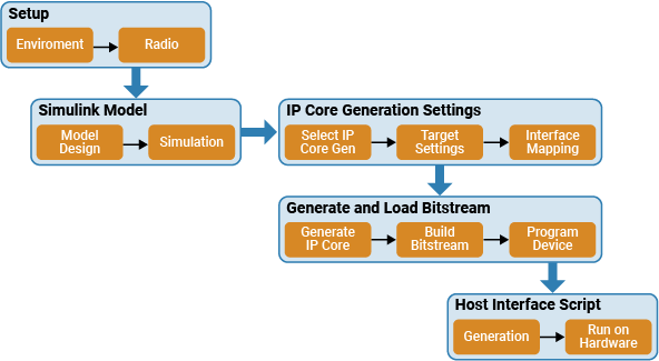
For more information about how to prototype and deploy software-defined radio algorithms on the FPGA of an NI USRP radio, see Target NI USRP Radios Workflow.
Design Overview
The example uses the algorithm from the Radar Target Emulator with HDL Coder (Radar Toolbox) example. The algorithm receives a linear FM pulse train and emulates up to four targets by applying variable range delays, Doppler shifts, and gains to the received waveform. Then, the algorithm retransmits the modified waveform at a known time offset. This design modifies the interfaces that enable you to deploy the generated bitstream on the FPGA of an NI USRP radio.

Open Simulink Model
The Simulink model implements the target emulation algorithm using a hardware modeling style and uses blocks that support HDL code generation. It uses fixed-point arithmetic and includes control signals that control the flow of data through the model.
Open the model from MATLAB.
open_system('wtRADARTargetEmulatorSL');

The model provides data for, and saves the output data from, the wtRADARTargetEmulatorSL subsystem.
Open the wtRADARTargetEmulatorSL subsystem.
open_system('wtRADARTargetEmulatorSL/wtRADARTargetEmulatorSL');

Data flows through these blocks and subsystems:
The AND block asserts the end of burst (EOB) signal on the last sample of the last packet of each burst.
The
Multiple Target Emulatorsubsystem emulates the response of four different targets.The
Sum Channelssubsystem combines the responses from the four targets into a single data stream.The Packetization block asserts the last signal every 256 valid samples or when the EOB signal is asserted.
The
Control retransmission time relative to receive timearea generates a timestamp for the retransmission of the next data packet from the radio by a fixed value that is controlled by the txTimeOffset port.
Open the Multiple Target Emulator subsystem.
open_system('wtRADARTargetEmulatorSL/wtRADARTargetEmulatorSL/Multiple Target Emulator');

The Multiple Target Emulator subsystem emulates the response for four different targets by applying a variable time delay, variable frequency shift, and variable attenuation according to the input enable, delay, inc, and gain ports. The operation is as follows:
When enable is true, the input data is provided to the variable time delay.
The variable time delay buffers the input samples in memory for the number of samples specified by the delay port.
The delayed data is multiplied by the output of an numerically controlled oscillator (NCO) to achieve a variable frequency shift. The NCO is controlled by the inc port value.
The delayed and shifted data is multiplied by the gain port value to achieve a variable attenuation.
open_system('wtRADARTargetEmulatorSL');

The inputs for each target are specified as input register ports on the wtRADARTargetEmulatorSL subsystem: e1, e2, e3, and e4 correspond to the enable input ports; d1, d2, d3, and d4 to the delay inputs; i1, i2, i3, and i4 to the inc input ports; and g1, g2, g3, and g4 to the gain input ports for each of the four targets respectively.
Simulate Design
Verify the design by simulating the model. Enable the four targets and specify the initial radar cross section (RCS), range, and speed.
targetEnabled = [true true true true]; % Set true to sim target
targetRCS = [1 2 3 4]; % dBsm
targetRange = [5e3 15e3 3e3 5e3]; % m
targetSpeed = [-200 -100 100 200]; % m/s
Set the maximum gain from which the relative gains applied by the model are based. This prevents unnecessary signal loss due to the fixed point data type and may be accounted for using the radio gain at the radio front end. Specify maxGain as empty to use the highest calculated real world gain in the helperRadarTargetSimulationSetup helper function.
maxGain = [];
Set the target emulation parameters used by the model in MATLAB by using the helperRadarTargetSimulationSetup helper function.
sl_in = helperRadarTargetSimulationSetup(targetEnabled,targetRCS,targetRange,targetSpeed,maxGain);
Run the Simulink model.
sl_out = sim("wtRADARTargetEmulatorSL.slx");
### Searching for referenced models in model 'wtRADARTargetEmulatorSL'.
### Total of 1 models to build.
### Building the rapid accelerator target for model: wtRADARTargetEmulatorSL
### Successfully built the rapid accelerator target for model: wtRADARTargetEmulatorSL
Process the simulation output data and plot the range-Doppler response using the helperVisualizeRadarTargetSimulation helper function.
Create a range-Doppler response object for processing data
rdResponse = phased.RangeDopplerResponse(...
    'DopplerFFTLengthSource','Property', ...
    'DopplerFFTLength',sl_in.VelDimLen, ...
    'PRFSource','Property', 'PRF',sl_in.PRF,...
    'SampleRate',sl_in.Fs,'DopplerOutput','Speed', ...
    'OperatingFrequency',sl_in.Fc);

% Create a 2D CFAR object for detection generation
cfar = phased.CFARDetector2D(GuardBandSize=[25 1],...
    TrainingBandSize=[10 1],...
    ProbabilityFalseAlarm=1e-4);

fig = figure;
ax = axes(fig);
helperVisualizeRadarTargetSimulation(sl_out,sl_in,rdResponse,cfar,0,ax);

Set Up Environment and Radio
To target an NI USRP radio with Wireless Testbench™, you must first install and configure additional toolboxes, support packages, and third-party tools. For more information, see Installation for Targeting NI USRP Radios.
If you have not previously saved a radio setup configuration for your radio hardware, use the radioSetupWizardradioConfigurations
Configure Model for IP Core Generation
First, use the hdlsetuptoolpath (HDL Coder) function to set up the Xilinx® tool chain. Specify the path to your Vivado® bin directory. For more information, see Set Up Third-Party Tools.
>> hdlsetuptoolpath('ToolName','Xilinx Vivado','ToolPath','/opt/Xilinx/Vivado/2021.1/bin');
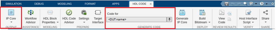
From the Apps tab in the Simulink Toolstrip, select HDLCoder. Open the HDL Code tab and follow these steps: # Ensure the wtRADARTargetEmulatorSL subsystem is pinned in the Code for option. To pin this selection, select the wtRADARTargetEmulatorSL subsystem in the Simulink model and click the pin icon. # Select IP Core as the Output > IP Core option.
Configure HDL Code Generation Settings
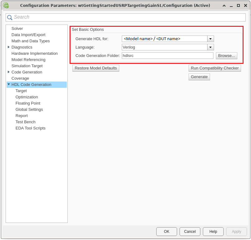
To open the Configuration Parameters window, click Settings in the HDL Code tab. Then, follow these steps:
In the basic options of the HDL Code Generation panel, ensure that Language is set to Verilog. By default, HDL Coder generates the Verilog files in the hdlsrc folder. You can select an alternative location. If you make any changes, click Apply.
In HDL Code Generation > Target > Workflow Settings, click Browse and select the project folder in which you want to save the generated project files.
In HDL Code generation > Target > Tool and Device Settings, set Target Platform to USRP X410. If you are using a different USRP radio, select the corresponding target platform and adjust the reference design parameters accordingly.
In the HDL Code generation > Target > Reference Design Settings, set Reference Design to X1_200 10GigE, or the desired reference FPGA image if you are using a different USRP radio. Set the reference design parameters with the following values:
External Memory - Set to
PL DDR Bufferto stream samples through the memory buffer on the radio. This setting ensures contiguous samples between MATLAB and the radio.Number of Input Streams - Set to
1because the DUT is connected to one data input stream.Number of Output Streams - Set to
1because the DUT is connected to one data output stream.Number of Antennas - Set to
1because the DUT has one radio receive and transmit channel.Sample Rate (S/s) - Set to
250e6or the desired baseband sampling rate for the target emulator hardware that the radio supports. For a list of supported sample rates, see Baseband Sample Rate in NI USRP Radios.BlockID - Set to any 32-bit hexadecimal number. The default is
12345678.DUT Clock Source - Set to
Radio. This option selects the master clock rate (MCR) of the radio front end as the DUT clock.Stream Port FIFO Length (Samples) - Set to
Auto.Register Port FIFO Length (Samples) - Set to
Auto.
In HDL Code generation > Target > Objective Settings, the target frequency is set by default to the maximum supported MCR of the radio.
Click Apply.

For more information, see Configure HDL Code Generation Settings.
Configure Target Interface
In the HDL Code tab, click Target Interface to open the IP Core editor.
In the Interface Mapping tab, reload the port interface mapping options by clicking
Reload IP core settings and interface mapping table from model:

Assign the input registers of the DUT as write registers.
Assign the data, valid, ready, last, end of burst (EOB), hastime, and timestamp signals for the input and output steaming interfaces.

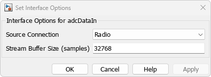
Each streaming interface data input and output port has an options menu. To retransmit the received samples, set the source and sink connection options to Radio. For the adcDataIn options, set the stream buffer size to 32768, which is the default setting. The buffer size must be a power of two to ensure optimal use of the FPGA RAM resources. The buffer size is specified in terms of the number of samples.
Validate the interface mapping by clicking Validate IP core settings and interface mapping:

Generate and Load Bitstream
To generate a bitstream from the IP core, first open the deployment settings from the Build Bitstream menu and ensure that the Run build process externally option is selected. This setting is the default and it ensures that the bitstream build executes in an external shell, which allows you to continue using MATLAB while building the FPGA image.

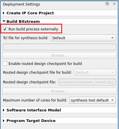
Click Build Bitstream to create a Vivado IP core project and build the bitstream. After the basic project checks complete, the Diagnostic Viewer displays a Build Bitstream Successful message along with warning messages. However, you must wait until the external shell displays a successful bitstream build before you proceed to the next step. The bitstream build process could take several hours. Closing the external shell before the indication of a successful build terminates the build. The bitstream for this project generates with the name x4xx.bit and is located in the build_X410_X1_200/build_X410_X1_200 folder of the working directory after a successful bitstream build.
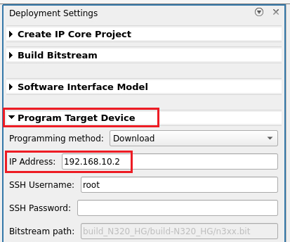
From Build Bitstream, open Deployment Settings. In the Program Target Device settings, set the IP address. The default is 192.168.10.2. If you changed the IP address from the default when you set up your hardware using the Radio Setup wizard, set the IP address accordingly.
To load the bitstream onto your radio, there are two options:
Load the bitstream in a later step using the generated host interface script, which calls the
programFPGAfunction.Load the bitstream onto the device now by clicking Program Target Device from the Build Bitstream menu.
If your radio is a USRP X310, it takes approximately five minutes to program your device. For other radios, it takes less than a minute. For more information, see Generate Bitstream and Program FPGA.
Generate and Modify Host Interface Scripts
To generate MATLAB scripts that enable you to connect to and run your deployed design on your radio, click Host Interface Script in the HDL Code tab. This generates an interface script file and setup function file that are specific to the target interface mapping of your IP core. For more information, see Run and Verify Hardware Implementation.
Run Host Interface Script
This example provides two ready-to-use live scripts for connecting to, configuring, and controlling your radio device with the target emulation algorithm deployed on the FPGA. You can chose to run and verify the DUT using a single radio, or use a second radio to transmit the test signals and receive the response.
Run and Verify DUT on Single Radio
Open RADARTargetEmulator_SingleDevice.mlx. Run this live script to transmit a radar pulse train from MATLAB, receive the pulse train into the target emulator DUT, transmit the target emulator response, and capture the response into MATLAB.
Plot the response and overlay the target locations and constant false alarm rate (CFAR) target detections to verify the operation of the DUT. The plot shows an example output.

open("./RADARTargetEmulator_SingleDevice.mlx")
Run DUT with External Stimulus
Open RADARTargetEmulator_MultiDevice.mlx. Run this live script to simulate a radar scenario in a background thread on one radio. Meanwhile, in the main MATLAB thread, configure a second radio as a baseband transceiver to transmit a radar pulse train and capture the response.

You can also use this approach to emulate target responses for other radio hardware.
open("./RADARTargetEmulator_MultiDevice.mlx")