wlanLSIGRecover
R2026bRecover L-SIG information bits
Syntax
Description
Examples
Recover L-SIG information transmitted in a noisy 2x2 MIMO channel, and calculate the number of bit errors present in the received information bits.
Set the channel bandwidth and sample rate.
chanBW = "CBW40";
fs = 40e6;
Create a VHT configuration object corresponding to a 40 MHz 2x2 MIMO channel.
cfg = wlanVHTConfig( ...
    ChannelBandwidth=chanBW, ...
    NumTransmitAntennas=2, ...
    NumSpaceTimeStreams=2);
Generate the L-LTF and L-SIG field signals.
txLLTF = wlanLLTF(cfg);
[txLSIG,txLSIGData] = wlanLSIG(cfg);
Create a 2x2 TGac channel
tgacChan = wlanTGacChannel(SampleRate=fs,ChannelBandwidth=chanBW, ...
    NumTransmitAntennas=2,NumReceiveAntennas=2,NormalizeChannelOutputs=false);
Pass the signals through the noisy 2x2 multipath fading channel.and add noise
snrdB = 10; % SNR (dB)
% Convert the SNR per active subcarrier to total SNR to account for noise energy in null subcarriers
ofdmInfo = wlanVHTOFDMInfo("VHT-LTF",cfg);
snrValue = convertSNR(snrdB,"snrsc","snr",FFTLength=ofdmInfo.FFTLength,NumActiveSubcarriers=ofdmInfo.NumTones);
nVar = 10^((-snrValue-30)/10); % Noise variance (W) for 0 dBm (-30 dBW) signal power
rxLLTF = awgn(tgacChan(txLLTF),snrValue);
rxLSIG = awgn(tgacChan(txLSIG),snrValue);
Perform channel estimation based on the L-LTF.
demodLLTF = wlanLLTFDemodulate(rxLLTF,chanBW,1);
chanEst = wlanLLTFChannelEstimate(demodLLTF,chanBW);
Recover the L-SIG information bits.
rxLSIGData = wlanLSIGRecover(rxLSIG,chanEst,nVar,chanBW);
Verify that there are no bit errors in the recovered L-SIG data.
numErrors = biterr(txLSIGData,rxLSIGData)
numErrors =
0
Recover L-SIG information using the zero-forcing equalizer algorithm. Calculate the number of bit errors in the received data.
Create an HT configuration object.
cfgHT = wlanHTConfig;
Generate the L-SIG field and pass it through an AWGN channel.
[txLSIG,txLSIGData] = wlanLSIG(cfgHT);
rxSIG = awgn(txLSIG,20);
Recover the L-SIG field using the zero-forcing algorithm. The channel estimate is a vector of ones because fading was not introduced.
chanEst = ones(52,1);
nVar = 0.1;
rxLSIGData = wlanLSIGRecover(rxSIG,chanEst,nVar,"CBW20",EqualizationMethod="ZF");
Verify that there are no bit errors in the recovered L-SIG data.
numErrors = biterr(txLSIGData,rxLSIGData)
numErrors =
0
Recover the L-SIG field from a channel that introduces a fixed phase and frequency offset.
Create a VHT configuration object corresponding to a 160 MHz SISO channel. Generate the transmitted L-SIG field.
cfgVHT = wlanVHTConfig(ChannelBandwidth="CBW160");
txLSIG = wlanLSIG(cfgVHT);
To introduce a 45 degree phase offset and a 100 Hz frequency offset, create a phase and frequency offset System object.
pfOffset = comm.PhaseFrequencyOffset(SampleRate=160e6,PhaseOffset=45, ...
    FrequencyOffset=100);
Introduce phase and frequency offsets to the transmitted L-SIG field, then pass it through an AWGN channel.
rxSIG = awgn(pfOffset(txLSIG),20);
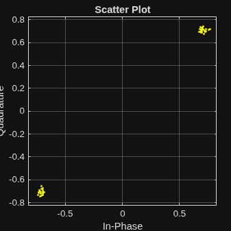
Recover the L-SIG information bits, the failure check status, and the equalized symbols, disabling pilot phase tracking.
chanEst = ones(416,1);
nVar = 0.01;
[recBits,failCheck,eqSym] = wlanLSIGRecover(rxSIG,chanEst,nVar,"CBW160",PilotPhaseTracking="None");
Verify that the L-SIG passed the failure checks.
disp(failCheck)
0
Visualize the phase offset by plotting the equalized symbols.
scatterplot(eqSym)
grid
Input Arguments
Name-Value Arguments
Output Arguments
More About
References
[1] IEEE Std 802.11™-2016 (Revision of IEEE Std 802.11-2012). “Part 11: Wireless LAN Medium Access Control (MAC) and Physical Layer (PHY) Specifications.” IEEE Standard for Information technology — Telecommunications and information exchange between systems — Local and metropolitan area networks — Specific requirements.
Extended Capabilities
Version History
Introduced in R2015b
See Also
wlanLSIG | wlanLLTF | wlanLLTFDemodulate | wlanLLTFChannelEstimate
1 IEEE Std 802.11-2020 Adapted and reprinted with permission from IEEE. Copyright IEEE 2020. All rights reserved.
2 © IEEE 2021. All rights reserved.
3 © IEEE 2021. All rights reserved.

