establishMAPCAgreement
R2026bDescription
establishMAPCAgreement( establishes
coordinated time division multiple access (Co-TDMA) multi-access point coordination (MAPC)
agreements between every pair of access points (APs) in the AP list. Once established, all
APs in the list can function as both coordinating and coordinated APs. For more information
about Co-TDMA, see How Does Co-TDMA Work?apList)
establishMAPCAgreement(
specifies the MAPC scheme apList,MAPCScheme=mapcScheme)mapScheme. Currently, the function supports
only the Co-TDMA scheme.
Examples
Coordinated time-division multiple access (Co-TDMA) is a technique that enables multiple Access Points (APs) to coordinate their transmissions, reducing interference and potentially improving overall throughput and latency. Simulate a wireless local area network (WLAN) with three APs capable of Co-TDMA and their associated stations (STAs). Both the APs and STAs are multi-link devices (MLDs). Configure the network, enable multi-AP coordination, run the simulation, and collect throughput and latency statistics at each node.
Create and Simulate Network
Set the seed for the random number generator to 1. The seed value controls the pattern of random number generation. The random number generated by the seed value impacts several processes within the simulation including backoff counter selection at the MAC layer and predicting packet reception success at the physical layer. To improve the accuracy of your simulation results, after running the simulation, you can change the seed value, run the simulation again, and average the results over multiple simulations.
rng(1,"combRecursive")Specify the simulation time in seconds.
simTime = 1; % Units are in secondsInitialize the network simulator.
networkSimulator = wirelessNetworkSimulator.init;
Create three AP MLDs and three STA MLDs. Configure each to operate on both the 5 GHz and 6 GHz bands.
% AP1 and STA1 apLinkCfg = wlanLinkConfig(BandAndChannel=[5 36; 6 1], .... BeaconInterval=50,TXOPLimit=[1 2 94 47],TransmissionFormat="EHT-SU", ... MCS=7,MPDUAggregationLimit=256); apMLDCfg = wlanMultilinkDeviceConfig(Mode="AP",LinkConfig=apLinkCfg,StandardCapability="UHR"); ap1 = wlanNode(DeviceConfig=apMLDCfg,Position=[0 0 0]); staLinkCfg = wlanLinkConfig(BandAndChannel=[5 36; 6 1],.... BeaconInterval=50,TXOPLimit=[1 2 94 47],TransmissionFormat="EHT-SU", ... MCS=7,MPDUAggregationLimit=256); staMLDCfg = wlanMultilinkDeviceConfig(Mode="STA",LinkConfig=staLinkCfg); sta1 = wlanNode(DeviceConfig=staMLDCfg,Position=[-2 -2 0]); % AP2 and STA2 apLinkCfg = wlanLinkConfig(BandAndChannel=[5 36; 6 1], ... BeaconInterval=50,TXOPLimit=[1 2 94 47],TransmissionFormat="EHT-SU", ... MCS=7,MPDUAggregationLimit=256); apMLDCfg = wlanMultilinkDeviceConfig(Mode='AP',LinkConfig=apLinkCfg,StandardCapability="UHR"); ap2 = wlanNode(DeviceConfig=apMLDCfg,Position=[5 0 0]); staLinkCfg = wlanLinkConfig(BandAndChannel=[5 36; 6 1], ... BeaconInterval=50,TXOPLimit=[1 2 94 47],TransmissionFormat="EHT-SU", ... MCS=7,MPDUAggregationLimit=256); staMLDCfg = wlanMultilinkDeviceConfig(Mode="STA",LinkConfig=staLinkCfg); sta2 = wlanNode(DeviceConfig=staMLDCfg,Position=[7 -2 0]); % AP3 and STA3 apLinkCfg = wlanLinkConfig(BandAndChannel=[5 36; 6 1], ... BeaconInterval=50,TXOPLimit=[1 2 3 4],TransmissionFormat="EHT-SU", ... MCS=7,MPDUAggregationLimit=256); apMLDCfg = wlanMultilinkDeviceConfig(Mode="AP",LinkConfig=apLinkCfg,StandardCapability="UHR"); ap3 = wlanNode(DeviceConfig=apMLDCfg,Position=[0 5 0]); staLinkCfg = wlanLinkConfig(BandAndChannel=[5 36; 6 1], ... BeaconInterval=50,TXOPLimit=[1 2 94 47],TransmissionFormat="EHT-SU", ... MCS=7,MPDUAggregationLimit=256); staMLDCfg = wlanMultilinkDeviceConfig(Mode="STA",LinkConfig=staLinkCfg); sta3 = wlanNode(DeviceConfig=staMLDCfg,Position=[-2 7 0]);
Associate each STA with its AP. Use associateStations for each AP-STA pair.
associateStations(ap1,sta1) associateStations(ap2,sta2) associateStations(ap3,sta3)
Create three On-Off application traffic pattern objects.
trafficSource1 = networkTrafficOnOff(DataRate=10000,PacketSize=100); trafficSource2 = networkTrafficOnOff(DataRate=10000,PacketSize=100); trafficSource3 = networkTrafficOnOff(DataRate=10000,PacketSize=100);
Configure traffic between the APs and STAs using the addTrafficSource function.
addTrafficSource(ap1,trafficSource1,DestinationNode=sta1,AccessCategory=2) addTrafficSource(ap2,trafficSource2,DestinationNode=sta2,AccessCategory=2) addTrafficSource(ap3,trafficSource3,DestinationNode=sta3,AccessCategory=2)
Establish an MAPC agreement for the Co-TDMA scheme between each pair of APs: ap1, ap2, and ap3. This enables any of these APs to initiate Co-TDMA operation.
establishMAPCAgreement([ap1 ap2 ap3],MAPCSchemes="Co-TDMA");Add the nodes to the simulator, and set up performance monitoring by using thehelperPerformanceViewer helper function.
nodes=[ap1 sta1 ap2 sta2 ap3 sta3]; addNodes(networkSimulator,nodes) perfViewer = helperPerformanceViewer(nodes,simTime);
Run the Simulation.
run(networkSimulator,simTime)
Check the throughput for each AP and latency for each STA.
% Throughput for each AP
throughput_ap1 = throughput(perfViewer,ap1.ID)throughput_ap1 = 9.9880
throughput_ap2 = throughput(perfViewer,ap2.ID)
throughput_ap2 = 3.4760
throughput_ap3 = throughput(perfViewer,ap3.ID)
throughput_ap3 = 9.0424
% Average receive latency for each STA
latency_sta1 = averageReceiveLatency(perfViewer,sta1.ID)latency_sta1 = 4.7124e-04
latency_sta2 = averageReceiveLatency(perfViewer,sta2.ID)
latency_sta2 = 0.0013
latency_sta3 = averageReceiveLatency(perfViewer,sta3.ID)
latency_sta3 = 0.0248
Input Arguments
List of APs, specified as a vector of wlanNode objects. The
DeviceConfig property of each node must be a
wlanMultilinkDeviceConfig object with the Mode property set to "AP" and the
StandardCapability property set to "UHR".
Note
When you set the value of the StandardCapability property
of the wlanMultilinkDeviceConfig to "UHR", specify the value
of theTransmissionFormat property of the wlanLinkConfig object as any value other than "auto"
for all transmissions from the link.
MAPC scheme, specified as "Co-TDMA".
Note
To enable Co-TDMA operation between APs, the wlanLinkConfig
object for at least one access category (AC) must have aTXOPLimit property with a nonzero value. Additionally, ensure that the
TXOPLimit value for AC VI is nonzero.
Algorithms
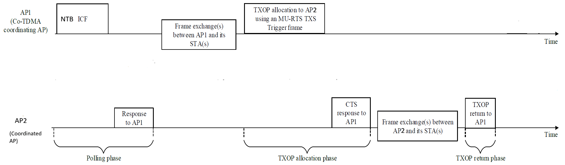
Co-TDMA operates in three phases.
Polling phase — The AP that currently owns the transmission opportunity (TXOP), known as the coordinating AP, initiates coordination by sending an initial control frame (ICF) to other APs. The intended APs that receive this ICF are coordinated APs. They respond with an initial control response (ICR) frame to indicate whether they wish to participate in TXOP sharing.
All APs participating in a MAPC agreement attempt Co-TDMA operation. An AP starts a TXOP with an ICF buffer status report poll (BSRP) non-trigger-based (NTB) for polling if all of these are true:
Beacon Reception — The AP has received at least one beacon with a received signal strength indicator (RSSI) ≥ –72 dBm from any AP participating in the MAPC agreement.
Beacon Configuration — All APs participating in the MAPC agreement enable beacons.
AC VI TXOP — AC VI has a nonzero TXOP.
Data Traffic TXOP — The AC that handles data traffic has a non-zero TXOP.
TXOP Duration — The configured TXOP limit values provide sufficient duration for the polling phase, the estimated data frame exchange, and the estimated minimum allocation phase. The equations for these phases are:
Tpolling = TBSRP + TMBA + (2×SIFS), where Tpolling represents the total time for the polling phase, TBSRP represents the time to transmit a Buffer Status Report Poll, TMBA represents the time to transmit a multi-STA block ack (MBA), and SIFS represents the short interframe space.
TDE = TFES × NFES, where TDE represents the estimated data frame exchange time with the associated STAs, TFES represents the time required for the next frame exchange sequence, and NFES is the ratio of the total number of MPDUs waiting in the queue to the number of MPDUs that can fit in the next frame exchange sequence.
Tallocation = TTimeMURTSCTS + TTimeData100B, where Tallocation represents the estimated allocation phase time, TTimeMURTSCTS represents the time required for multi-user request to send (MU-RTS) triggered TXOP sharing (TXS) and clear to send (CTS) exchange, and TTimeData100B represents time required for a 100-byte data frame exchange sequence (including RTS transmission and CTS response) using non-high throughput at 6 Mbps.
A coordinated AP evaluates the polling request and rejects the polling when either condition applies.
The AP has no frames to transmit.
The duration indicated in the Max TXOP allocation (under consideration) parameter of the ICF frame cannot accommodate at least one aggregated medium access control (MAC) protocol data unit (A-MPDU) containing one MPDU.
TXOP allocation phase — After collecting poll responses and completing frame exchanges with its own associated stations, the coordinating AP allocates the remaining time to a coordinated AP by sending an MU-RTS TXS trigger frame. The coordinated AP responds with a CTS, then utilizes the shared TXOP to perform frame exchanges with its associated stations.
To allocate a TXOP to a coordinated AP, a coordinating AP must satisfy all of the following conditions:
The coordinating AP has finished its own scheduled transmissions.
The coordinated AP has requested TXOP sharing during the polling phase.
The coordinating AP has used at least 33% of its TXOP limit.
The remaining TXOP time is enough to perform a frame exchange sequence for at least a 100-byte data frame (including RTS/ CTS exchange).
TXOP return phase — If a coordinated AP completes its transmission before using its entire allocated TXOP, it can return the unused portion of the TXOP to the coordinating AP.
When possible, a coordinated AP returns the TXOP to the user using these steps.
The coordinated AP sends a TXOP Return Action frame to the coordinating AP, provided sufficient time remains to complete the transmission.
If sufficient time remains, the coordinating AP then transmits a contention-free (CF) End frame to terminate the TXOP.
Note that all communication between APs uses a data rate of 24 Mbps, which is the highest mandatory basic rate for Non-HT modes. This applies to frames such as BSRP NTB, MU-RTS TXS, MAPC TXOP return, and their corresponding responses. The only exception is the CTS response to MU-RTS, which the standard restricts to 6 Mbps.
This diagram illustrates the Co-TDMA operation for two APs.
Version History
Introduced in R2026b
MATLAB Command
You clicked a link that corresponds to this MATLAB command:
Run the command by entering it in the MATLAB Command Window. Web browsers do not support MATLAB commands.
选择网站
选择网站以获取翻译的可用内容,以及查看当地活动和优惠。根据您的位置,我们建议您选择:。
您也可以从以下列表中选择网站:
如何获得最佳网站性能
选择中国网站(中文或英文)以获得最佳网站性能。其他 MathWorks 国家/地区网站并未针对您所在位置的访问进行优化。
美洲
- América Latina (Español)
- Canada (English)
- United States (English)
欧洲
- Belgium (English)
- Denmark (English)
- Deutschland (Deutsch)
- España (Español)
- Finland (English)
- France (Français)
- Ireland (English)
- Italia (Italiano)
- Luxembourg (English)
- Netherlands (English)
- Norway (English)
- Österreich (Deutsch)
- Portugal (English)
- Sweden (English)
- Switzerland
- United Kingdom (English)