Main Content

wlanNonHTData

Generate non-HT-Data field waveform

Description

example

y = wlanNonHTData(psdu,cfg) generates a non-HT Data field time-domain waveform for PSDU bits psdu and non-HT transmission parameters cfg.

example

y = wlanNonHTData(psdu,cfg,scramInit) specifies the scrambler initialization state.

y = wlanNonHTData(___,OversamplingFactor=osf) generates an oversampled non-HT Data field waveform for the specified oversampling factor. For more information about oversampling, see FFT-Based Oversampling.

Examples

collapse all

Generate the waveform for a 20MHz non-HT-Data field for 36 Mbps.

Create a non-HT configuration object and assign MCS to 5.

cfg = wlanNonHTConfig('MCS',5);

Assign random data to the PSDU and generate the data field waveform.

psdu = randi([0 1],cfg.PSDULength*8,1);
y = wlanNonHTData(psdu,cfg);
size(y)
ans = 1×2

        4480           1

Configure transmission parameters by creating a wlanNonHTConfig object, specifying a channel bandwidth of 80 MHz and static bandwidth operation.

cfg = wlanNonHTConfig('ChannelBandwidth','CBW80','SignalChannelBandwidth',true, ... 
     'BandwidthOperation','Static');

Generate a random PSDU of the appropriate length.

psdu = randi([0 1],8*cfg.PSDULength,1,'int8');

Generate the initial pseudorandom scrambler sequence.

[range,numBits] = scramblerRange(cfg);
scramInit = randi(range);

Generate the non-HT Data field signal.

y = wlanNonHTData(psdu,cfg,scramInit);

Input Arguments

collapse all

Physical layer convergence procedure (PLCP) service data unit (PSDU) bits, specified as a binary-valued column vector of length 8 × L, where L is the PSDU length in bytes. To specify L, set the PSDULength property of the cfg input.

Data Types: double

Non-HT transmission parameters, specified as a wlanNonHTConfig object.

Initial scrambler state or initial pseudorandom scrambler sequence for each generated packet.

When you disable bandwidth signaling by setting the SignalchannelBandwidth property of the cfg input to 0 (false), this input represents the initial scrambler state. In this case, this input must be an integer in the interval [1, 127], or as the corresponding binary-valued column vector of length seven. The default value, 93, is the example state in section I.1.5.2 of [1].

When you enable bandwidth signaling by setting the SignalchannelBandwidth property of the cfg input to 1 (true), this input represents the pseudorandom scrambler sequence described in Table 17-7 of [1]. In this case, this input must be an integer in the interval [min, max], or the corresponding binary-valued column vector of length NB. The values of min, max, and NB depend on the values of the BandwidthOperation and ChannelBandwidth properties of the cfg input according to this table.

Value of cfg.BandwidthOperationValue of cfg.ChannelBandwidthValue of minValue of maxValue of NB
'Absent''CBW20'1315
'Absent''CBW5', 'CBW10', 'CBW40', 'CBW80', or 'CBW160'0315
'Static' or 'Dynamic''CBW20'1154
'Static' or 'Dynamic''CBW5', 'CBW10', 'CBW40', 'CBW80', or 'CBW160'0154

If you do not specify this input, the function uses the NB most significant bits of the default value, 93.

Section 17.3.5.5 of [1] specifies the scrambling and descrambling process applied to the transmitted data. The header and data fields that follow the scrambler initialization field (including data padding bits) are scrambled by XORing each bit with a length-127 periodic sequence generated by the polynomial S(x) = x7 + x4 + 1. The octets of the PSDU are placed into a bit stream, and, within each octet, bit 0 (LSB) is first and bit 7 (MSB) is last. This figure demonstrates the sequence generation and XOR operation.

Generate a periodic sequence of length 127 by using the XOR operation

Conversion from integer to bits uses left-MSB orientation. For example, initializing the scrambler with decimal 1, the bits map to these elements.

ElementX7X6X5X4X3X2X1
Bit Value0000001

To generate the bit stream equivalent to a decimal, use the int2bit function. For example, for decimal 1:

int2bit(1,7)'
ans =

     0     0     0     0     0     0     1

Example: [1; 0; 1; 1; 1; 0; 1] conveys the scrambler initialization state of 93 as a binary vector.

Data Types: double | int8

Oversampling factor, specified as a scalar greater than or equal to 1. The oversampled cyclic prefix length must be an integer number of samples.

Data Types: single | double | int8 | int16 | int32 | int64 | uint8 | uint16 | uint32 | uint64

Output Arguments

collapse all

Non-HT Data field time-domain waveform, returned as a complex-valued matrix of size NS-by-NT.

  • NS is the number of time domain samples

  • NT is the number of transmit antennas.

Data Types: double
Complex Number Support: Yes

More About

collapse all

PSDU

Physical layer (PHY) service data unit (PSDU). This field is composed of a variable number of octets. The minimum is 0 (zero) and the maximum is 2500. For more information, see IEEE Std 802.11™-2012, Section 15.3.5.7.

Non-HT Data field

The non-high throughput Data (non-HT Data) field is used to transmit MAC frames and is composed of a service field, a PSDU, tail bits, and pad bits.

The Non-HT Data field

  • Service field — Contains 16 zeros to initialize the data scrambler.

  • PSDU — Variable-length field containing the PLCP service data unit (PSDU).

  • Tail — Tail bits required to terminate a convolutional code. The field uses six zeros for the single encoding stream.

  • Pad Bits — Variable-length field required to ensure that the non-HT data field contains an integer number of symbols.

Algorithms

collapse all

Non-HT Data Field Processing

The non-HT Data field follows the L-SIG in the packet. For algorithm details, refer to section 17.3.5 of [1]. The non-HT Data includes the user payload in the PSDU plus 16 service bits, six tail bits, and additional padding bits as required to fill out the last OFDM symbol. The function performs transmitter processing on the non-HT Data field and generates the time-domain waveform.

Transmitter processing steps on the non-HT data field

FFT-Based Oversampling

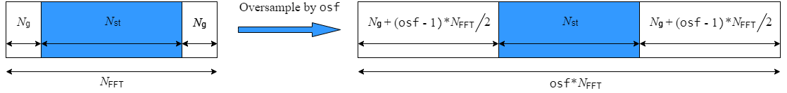
An oversampled signal is a signal sampled at a frequency that is higher than the Nyquist rate. WLAN signals maximize occupied bandwidth by using small guardbands, which can pose problems for anti-imaging and anti-aliasing filters. Oversampling increases the guardband width relative to the total signal bandwidth, thereby increasing the number of samples in the signal.

This function performs oversampling by using a larger IFFT and zero pad when generating an OFDM waveform. This diagram shows the oversampling process for an OFDM waveform with NFFT subcarriers comprising Ng guardband subcarriers on either side of Nst occupied bandwidth subcarriers.

FFT-based oversampling

References

[1] IEEE Std 802.11™-2020 (Revision of IEEE Std 802.11-2016). “Part 11: Wireless LAN Medium Access Control (MAC) and Physical Layer (PHY) Specifications.” IEEE Standard for Information Technology — Telecommunications and Information Exchange between Systems — Local and Metropolitan Area Networks — Specific Requirements.

Extended Capabilities

C/C++ Code Generation
Generate C and C++ code using MATLAB® Coder™.

Version History

Introduced in R2015b