802.11ah Waveform Generation
This example shows how to generate IEEE® 802.11ah™ S1G waveforms and highlights some of the key features of the standard.
Introduction
802.11ah is intended for extended range and low power applications in the unlicensed sub 1 GHz band, including machine to machine communication and the internet of things. 802.11ah uses narrower contiguous channel bandwidths than 802.11n™ and 802.11ac™ to facilitate long range, low power communication at a lower data rate. Valid channel bandwidths are 1, 2, 4, 8, and 16 MHz.
Since 802.11ah uses the same underlying physical layer technologies as 802.11n and 802.11ac, the processing chains are very similar. With the exception of 1 MHz transmissions, in general data is modulated using the same process as in 802.11ac with a 1/10 clock rate.
In this example a number of 802.11ah S1G [ 1 ] waveforms are generated to highlight some of the key modes and features of the 802.11ah standard.
802.11ah Modes and PHY Features
The 802.11ah standard defines three modes:
The 1 MHz mode (S1G_1M) is intended for low data rate applications. This mode features an extended preamble and a new modulation and coding scheme, MCS10, to improve robustness. MCS10 is BPSK 1/2 rate with 2 times repetition. When MCS10 is used the short training field (STF) is boosted by 3 dB to allow for packet detection [ 2 ]. In this mode the whole PPDU is beamformed.
The >= 2 MHz long preamble mode (S1G_LONG) is used for single or multi-user transmissions with a 2, 4, 8, or 16 MHz channel bandwidth. The PPDU is similar to a 802.11ac VHT PPDU, consisting of an omni-directional portion and beam-changeable portion.
The >= 2 MHz short preamble mode (S1G_SHORT) is used for single-user transmissions with a 2, 4, 8, or 16 MHz channel bandwidth. In this mode the whole PPDU is beamformed.
The 802.11ah standard is intended to operate outdoors as well as indoors. Traveling Pilots have been introduced to compensate for Doppler spread caused by reflections due to vehicular motion. In previous 802.11 standards the pilot locations are fixed to the same subcarrier for the duration of a packet. Tracking the varying channel conditions due to a high Doppler environment is not effective with fixed pilot locations. Traveling pilots change the subcarriers that carry the pilots over time which improves the ability to track changing channel conditions. In this example a waveform is generated for each of the three modes introduced above with configurations for MCS10 and traveling pilot highlighted.
S1G 1MHz Mode
An S1G 1 MHz PPDU consists of five fields, all of which can be beamformed:
STF - The short training field, which is used for coarse synchronization
LTF1 - The first long training field, which is used for fine synchronization and initial channel estimation
SIG - The signaling field, which the receiver decodes to determine transmission parameters
LTF2-N - The subsequent long training fields, which is used for MIMO channel estimation
Data - The data field, which carries the user data payload
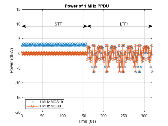
Examples of waveform generation for MCS0 and MCS10 1 MHz transmissions are shown. When MCS10 is used a 3 dB power boost is applied to the short training field. This power boost will be visualized.
The function wlanWaveformGenerator returns an S1G configuration object. Create an S1G configuration object for 1 MHz bandwidth, 1 transmit antenna, 1 space-time stream, BPSK rate 1/2 (MCS0), and a 256 byte APEP length.
cfg1MHz = wlanS1GConfig;
cfg1MHz.ChannelBandwidth = 'CBW1';
cfg1MHz.NumTransmitAntennas = 1;
cfg1MHz.NumSpaceTimeStreams = 1;
cfg1MHz.MCS = 0;
cfg1MHz.APEPLength = 256;
Create a PSDU of random bits using the required length for the specified format configuration.
psdu = randi([0 1],cfg1MHz.PSDULength*8,1);
Generate an S1G waveform using the configured S1G format object and PSDU as inputs to the waveform generator, wlanWaveformGenerator. The waveform generator modulates PSDU bits according to a format configuration. The waveform generator also performs OFDM windowing. In this example windowing is disabled for clearer visualization.
% Generate waveform with windowing disabled
txMCS0 = wlanWaveformGenerator(psdu,cfg1MHz,'WindowTransitionTime',0);
Change the MCS of cfg1MHz to 10 and generate a second waveform to demonstrate the STF power boost.
cfg1MHz.MCS = 10;
txMCS10 = wlanWaveformGenerator(psdu,cfg1MHz,'WindowTransitionTime',0);
The power is plotted for the first 320 microseconds of both waveforms to capture the duration of the STF and first LTF in the 1 MHz transmission. Note the power boost of the STF when MCS10 is used. The power boost is required to obtain sufficient packet detection sensitivity to support MCS10 [ 2 ].
t = 320; % Duration to plot in microseconds
sr = wlanSampleRate(cfg1MHz); % Sample rate Hz
tick = (1/sr)*1e6; % Microseconds per sample
hf = figure;
hp(1) = plot(0:tick:t-tick,20*log10(abs(txMCS10(1:t*sr*1e-6,:))),'x-');
hold on;
hp(2) = plot(0:tick:t-tick,20*log10(abs(txMCS0(1:t*sr*1e-6,:))),'o-');
xlim([0 t-1]);
ylim([-20 15]);
s1gWavGenPlotFieldOverlay(cfg1MHz,hf);
grid on;
legend(hp,'1 MHz MCS10','1 MHz MCS0','Location','SouthWest');
title('Power of 1 MHz PPDU');
xlabel('Time (us)');
ylabel('Power (dBW)');
S1G >=2 MHz Long Preamble Mode
The 802.11ah long preamble supports single and multi-user transmissions. The long preamble PPDU consists of two portions; the omni-directional portion and the beam-changeable portion.
The omni-directional portion is transmitted to all users without beamforming. It consists of three fields:
STF - The short training field, which is used for coarse synchronization
LTF1 - The first long training field, which is used for fine synchronization and initial channel estimation
SIG-A - The signaling A field, which the receiver decodes to determine transmission parameters relevant to all users
The beam-changeable portion can be beamformed to each user. It consists of four fields:
D-STF - The beamformed short training field, which is used by the receiver for automatic gain control
D-LTF - The beamformed long training fields, which is used for MIMO channel estimation
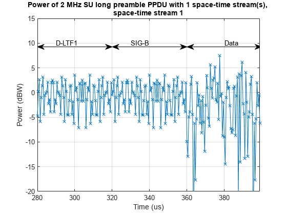
SIG-B - The signaling B field. In a multi-user transmission the SIG-B signals the MCS for each user. In a single-user transmission the MCS is signaled in the SIG-A field of the omni-directional portion of the preamble. Therefore in a single-user transmission the SIG-B symbol transmitted is an exact repetition of the first D-LTF. This repetition allows for improved channel estimation.
Data - The data field, which carries the user data payload
To visualize repetition of the first D-LTF an S1G 2 MHz long preamble format configuration object is created using the wlanS1GConfig function and configured for one space-time stream and one transmit antenna.
cfgSU = wlanS1GConfig;
cfgSU.ChannelBandwidth = 'CBW2';
cfgSU.Preamble = 'Long';
cfgSU.NumUsers = 1;
cfgSU.NumSpaceTimeStreams = 1;
cfgSU.NumTransmitAntennas = 1;
cfgSU.MCS = 1;
cfgSU.APEPLength = 150;
The >=2 MHz long preamble waveform with a single space-time stream is generated using the cfgSU object.
% Generate a PSDU containing random bits
psdu = randi([0 1],cfgSU.PSDULength*8,1);

% Generate a PPDU waveform
txSU = wlanWaveformGenerator(psdu,cfgSU);
The D-LTF and SIG-B fields are plotted. Note the repetition of the D-LTF in the SIG-B symbol.
s1gWavGenPlotSIGB(cfgSU,txSU);
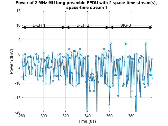
As a comparison a 2 MHz long preamble multi-user waveform will be generated and visualized. First, a format configuration object is created for two users. The user positions, number of space times streams, MCS and APEP length are configured per user using vectors to parameterize the relevant properties of the cfgMU object.
cfgMU = wlanS1GConfig;
cfgMU.ChannelBandwidth = 'CBW2';
cfgMU.Preamble = 'Long';
cfgMU.NumUsers = 2;
cfgMU.UserPositions = [0 1];
cfgMU.NumSpaceTimeStreams = [1 1];
cfgMU.NumTransmitAntennas = sum(cfgMU.NumSpaceTimeStreams);
cfgMU.MCS = [1 2];
cfgMU.APEPLength = [150 250];
A random PSDU is created for each user and a multi-user waveform is generated. The PSDU length for each user, cfgMU.PSDULength, is calculated based on transmission properties by the cfgMU object.
% Generate cell array containing the PSDUs for all users
psdu = cell(cfgMU.NumUsers,1);
for i = 1:cfgMU.NumUsers
    psdu{i} = randi([0 1],cfgMU.PSDULength(i),1);
end

% Generate waveform
txMU = wlanWaveformGenerator(psdu,cfgMU);
The two D-LTF fields and SIG-B fields are plotted for the first space-time stream. Note the SIG-B symbol is no longer a repetition of D-LTF1 as it carries the MCS per user.
s1gWavGenPlotSIGB(cfgMU,txMU);
S1G >=2 MHz Short Preamble Mode
An S1G >=2 MHz short preamble waveform consists of five fields, all of which can be beamformed:
STF - The short training field, which is used for coarse synchronization
LTF1 - The first long training field, which is used for fine synchronization and initial channel estimation
SIG - The signaling field, which the receiver decodes to determine transmission parameters
LTF2-N - The subsequent long training fields, which is used for MIMO channel estimation
Data - The data field, which carries the user data payload
In this example S1G 2 MHz short preamble waveforms with and without traveling pilots will be generated.
Traveling pilots are an optional feature for all three S1G modes to allow for outdoor links where Doppler spread is potentially introduced due to moving vehicles. The traveling pilots are boosted 1.5 times compared to fixed pilots to improve channel estimation performance in this environment [ 3 ].
Two >= 2 MHz short preamble waveforms are generated; one with fixed pilots and one with traveling pilots. First a S1G 2 MHz short preamble format configuration with fixed pilot locations is created using the wlanS1GConfig object.
cfgFix = wlanS1GConfig;
cfgFix.ChannelBandwidth = 'CBW2';
cfgFix.Preamble = 'Short';
cfgFix.NumTransmitAntennas = 1;
cfgFix.NumSpaceTimeStreams = 1;
cfgFix.MCS = 0; % BPSK so same power on all subcarriers for analysis
cfgFix.APEPLength = 100;
cfgFix.TravelingPilots = false; % Fixed pilot subcarriers
Generate a fixed pilot waveform using the cfgFix object and random PSDU bits. The PSDU bits are created using the required length for the specified format configuration.
% Generate a PSDU containing random bits
psdu = randi([0 1],cfgFix.PSDULength*8,1);

% Generate a PPDU waveform
txFix = wlanWaveformGenerator(psdu,cfgFix);
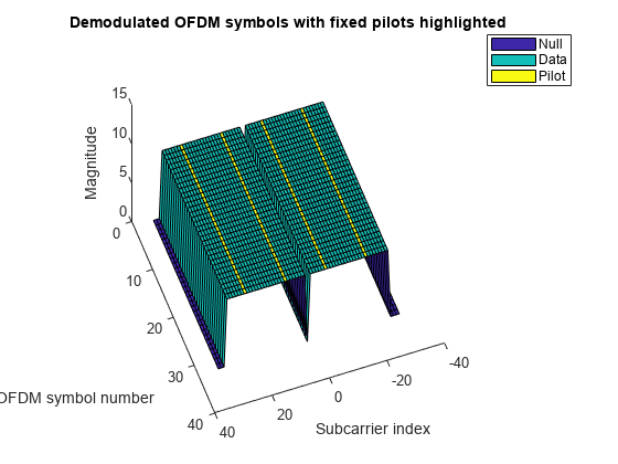
Extract the data field from the time domain waveform using the known duration of the preamble. Plot the magnitude of the OFDM symbols and subcarriers. The location of nulls, data carrying subcarriers, and pilot carrying subcarriers are highlighted. The pilot locations remain unchanged for the duration of the packet.
s1gWavGenPlotGrid(txFix,cfgFix, ...
    'Demodulated OFDM symbols with fixed pilots highlighted')
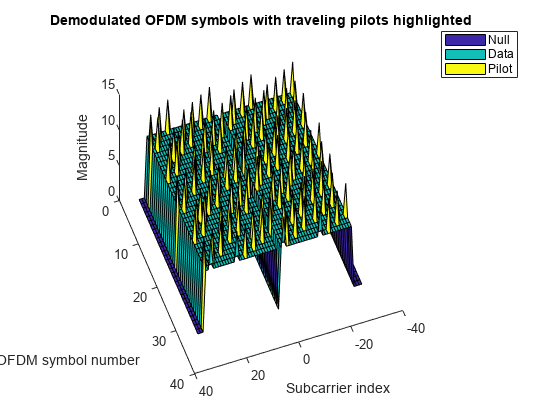
Now a waveform is generated using the same configuration but with traveling pilots. This could be accomplished by changing the TravelingPilots property of the existing configuration object and regenerating the waveform, but in this example a separate object is created and used.
% Copy the format configuration object and enable traveling pilots
cfgTravel = cfgFix;
cfgTravel.TravelingPilots = true;

% Generate waveform with traveling pilots
txTravel = wlanWaveformGenerator(psdu,cfgTravel);
The magnitude of the OFDM symbols and subcarriers is plotted again. The pilot locations now change per OFDM symbol. The magnitude of pilot subcarriers is 1.5 times that of data carrying subcarriers.
s1gWavGenPlotGrid(txTravel,cfgTravel, ...
    'Demodulated OFDM symbols with traveling pilots highlighted')
Conclusion
This example has demonstrated how to generate waveforms for different 802.11ah S1G modes and highlighted some of the key features of the standard.
Selected Bibliography
IEEE P802.11ah™/D5.0 Draft Standard for Information technology - Telecommunications and information exchange between systems - Local and metropolitan area networks - Specific requirements - Part 11: Wireless LAN Medium Access Control (MAC) and Physical Layer (PHY) Specifications. Amendment 2: Sub 1 GHz License Exempt Operation.
Sameer Vermani et al. "Preamble Format for 1 MHz", IEEE 802.11-11/1482r4, 2012-01-16.
Ron Porat et al. "Traveling Pilots", IEEE 8902.11-12/1322r0, 2012-11-12.