802.11ax Compressed Beamforming Packet Error Rate Simulation
This example shows how to measure the packet error rate of a beamformed IEEE® 802.11ax™ high efficiency single user (HE SU) format link with different beamforming feedback quantization levels.
Introduction
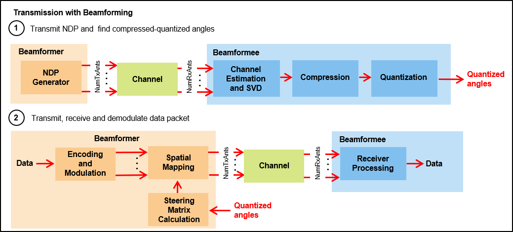
Transmit beamforming focuses energy towards a receiver to improve the SNR of a link. In this scheme, the transmitter is called a beamformer and the receiver is called a beamformee. A steering matrix is used by the beamformer to direct the energy to the beamformee. The steering matrix is calculated using channel state information (CSI) obtained through channel measurements. These measurements are obtained by sounding the channel between beamformer and beamformee. To sound the channel, the beamformer sends a null data packet (NDP) to the beamformee. The beamformee measures the channel information during sounding to calculate a feedback matrix. This matrix is compressed in the form of quantized angles (phi and psi) and fed back to the beamformer. The beamformer can then calculate the feedback matrix from the quantized angles to create a steering matrix and beamform transmissions to the beamformee. The process of forming steering matrix is shown in 802.11ac Transmit Beamforming. The process of using AI/ML technique to compress CSI feedback in IEEE® 802.11be™ SU-MIMO beamforming scenario is shown in CSI Feedback Compression for 802.11be Using AI.
802.11ax uses subcarrier grouping technique for compressed beamforming feedback. Instead of estimating and then sending the compressed feedback matrix on all subcarriers the beamformee sends the compressed feedback matrix on a group of subcarriers (4 or 16, see section 9.4.1.65 of [1]) to the beamformer. This reduces the amount of channel information feedback from the beamformee to the beamformer. The beamformer reconstructs the compressed feedback matrix on all subcarriers by interpolating the subcarriers that are not reported due to grouping. The beamformer creates a steering matrix from the feeback matrix, which beamforms transmission to the beamformee.
This example measures the packet error rate (PER) for an 802.11ax [1] single-user (SU) link comprising a 4x2 MIMO configuration between a transmitter and receiver with two space-time streams. The link utilizes compressed beamforming feedback quantization for different quantization levels and a selection of SNR points. The example simulates sending CSI on all subcarriers (Ng=1, no grouping and compressed beamforming feedback quantization) and grouped subcarriers (Ng=4, with compressed beamforming feedback quantization).
Waveform Configuration
An HE SU packet is a full-band transmission to a single user. Configure transmit parameters for the HE SU format using a wlanHESUConfig object. Configure the object for a 20 MHz channel bandwidth, four transmit antennas, two space-time streams, 16-QAM rate-1/2 (MCS 3), and 4x HE-LTF compression mode. This example does not model subcarrier beamforming smoothing.
NumTxAnts = 4; % Number of transmit antennas
NumSTS = 2;    % Number of space-time streams
NumRxAnts = 2; % Number of receive antennas
Ng = 4;        % Subcarrier grouping. Ng must be 1 (no grouping), 4, or 16.
cfgHEBase = wlanHESUConfig;
cfgHEBase.ChannelBandwidth = 'CBW20';      % Channel bandwidth
cfgHEBase.NumSpaceTimeStreams = NumSTS;    % Number of space-time streams
cfgHEBase.NumTransmitAntennas = NumTxAnts; % Number of transmit antennas
cfgHEBase.APEPLength = 1e3;                % Payload length in bytes
cfgHEBase.ExtendedRange = false;           % Do not use extended range format
cfgHEBase.Upper106ToneRU = false;          % Do not use upper 106 tone RU
cfgHEBase.PreHESpatialMapping = false;     % Spatial mapping of pre-HE fields
cfgHEBase.GuardInterval = 3.2;             % Guard interval duration
cfgHEBase.HELTFType = 4;                   % HE-LTF compression mode
cfgHEBase.ChannelCoding = 'LDPC';          % Channel coding
cfgHEBase.MCS = 3;                         % Modulation and coding scheme
cfgHEBase.SpatialMapping = 'Custom';       % Custom for beamforming
Null Data Packet (NDP) Configuration
Configure the NDP transmission to have data length of zero. Since the NDP is used to obtain the channel state information, set the number of space-time streams equal to the number of transmit antennas and directly map each space-time stream to a transmit antenna.
cfgNDP = cfgHEBase;
cfgNDP.APEPLength = 0;                  % NDP has no data
cfgNDP.NumSpaceTimeStreams = NumTxAnts; % For feedback matrix calculation
cfgNDP.SpatialMapping = 'Direct';       % Each TxAnt carries a STS
Channel Configuration
This example uses a TGax NLOS indoor channel model with delay profile Model-B. The Model-B profile is considered NLOS when the distance between transmitter and receiver is greater than or equal to five meters. For more information, see wlanTGaxChannel.
% Create and configure the TGax channel
chanBW = cfgHEBase.ChannelBandwidth;
tgaxChannel = wlanTGaxChannel;
tgaxChannel.DelayProfile = 'Model-B';
tgaxChannel.NumTransmitAntennas = NumTxAnts;
tgaxChannel.NumReceiveAntennas = NumRxAnts;
tgaxChannel.TransmitReceiveDistance = 5; % Distance in meters for NLOS
tgaxChannel.ChannelBandwidth = chanBW;
tgaxChannel.LargeScaleFadingEffect = 'None';
tgaxChannel.NormalizeChannelOutputs = false;
fs = wlanSampleRate(cfgHEBase);
tgaxChannel.SampleRate = fs;
Simulation Parameters
This example compares the performance of beamforming with two different resolutions of compression quantization, and without compression. For each quantization resolution, perform an end-to-end simulation with various SNR values to determine the PER. 802.11ax specifies only two sets of quantization resolution for single user beamforming (Table 9-29a in [1]). Set the value of codeBookSize to select the number of bits used to quantize the beamforming feedback angles (phi and psi) in this simulation. To disable compression set codeBookSize to Inf. This table shows the quantization levels for each value of codeBookSize:
codeBookSize            Compression Configuration            Subcarrier Grouping
---------------------------------------------------------------------------------
    0                   NumBitsphi = 4; NumBitspsi = 2       4
    1                   NumBitsphi = 6; NumBitspsi = 4       4
   Inf                  No compression                       No grouping (Ng=1)
---------------------------------------------------------------------------------
codeBookSize = [0 1 Inf];
Set the SNRs to simulate in dB.
snr = 10:2:18;
Limit the number of packets tested at each SNR point to maxNumErrors or maxNumPackets, where:
maxNumErrorsis the maximum number of packet errors simulated at each SNR point. When the number of packet errors reaches this limit, the simulation at this SNR point is complete.maxNumPacketsis the maximum number of packets simulated at each SNR point and limits the length of the simulation if the packet error limit is not reached.
The numbers chosen in this example lead to a very short simulation. For statistically meaningful results, increase these numbers.
maxNumErrors = 10;   % The maximum number of packet errors at an SNR point
maxNumPackets = 100; % The maximum number of packets at an SNR point
Processing SNR Points
For each SNR point, test packets and calculate the PER. For each packet, perform these steps.
Obtain the steering matrix to create a feedback matrix:
Transmit an NDP waveform through an indoor TGax channel model. Model different channel realizations for different packets.
Add AWGN to the received waveform to create the desired average SNR per active subcarrier after OFDM demodulation.
Detect the packet at the beamformee.
Estimate and correct for coarse carrier frequency offset (CFO).
Establish fine timing synchronization.
Estimate and correct for fine CFO.
Extract the HE-LTF from the synchronized received waveform. OFDM demodulate the HE-LTF and perform channel estimation.
Perform singular value decomposition on the estimated channel at grouped subcarriers and calculate the beamforming feedback matrix, V.
Compress and quantize the feedback matrix, V, to create a set of angles as specified in the standard.
Transmit a data packet using the recovered steering matrix and decode the beamformed data transmission to recover the PSDU:
If modeling compression, convert the quantized angles back to the beamforming feedback matrix, V, for all subcarriers. Otherwise, use the V matrix calculated by the beamformee. Assume no beamforming feedback delay.
Construct the beamforming feedback matrix, V, on all subcarriers by interpolating the subcarriers that are not reported due to grouping (
Ng4 or 16).Create and encode a PSDU to create a single-packet waveform with the steering matrix set to the beamforming feedback matrix, V.
Pass the waveform through the same indoor TGax channel realization as the NDP transmission.
Add AWGN to the received waveform.
As with NDP, perform synchronization and HE channel estimation.
Extract the data field from the synchronized received waveform and OFDM demodulate.
Perform common phase error pilot tracking to track any residual carrier frequency offset.
Estimate the noise power using the demodulated data field pilots and single-stream channel estimate at pilot subcarriers.
Equalize the phase corrected OFDM symbols with the channel estimate.
Demodulate and decode the equalized symbols to recover the PSDU.
To parallelize processing of SNR points, you can use a parfor loop. To enable the use of parallel computing for increased speed comment out the 'for' statement and uncomment the 'parfor' statement below.
numQuant = numel(codeBookSize);
numSNR = numel(snr); % Number of SNR points
packetErrorRate = zeros(numQuant,numSNR);

% Get occupied subcarrier indices and OFDM parameters
ofdmInfo = wlanHEOFDMInfo('HE-Data',cfgHEBase);
groupedSCIndices = helperCompressedBeamformingSubcarrierIndices(cfgNDP,Ng);

% Indices to extract fields from the PPDU
ind = wlanFieldIndices(cfgHEBase);
indSound = wlanFieldIndices(cfgNDP);

for ibf = 1:numQuant
    switch codeBookSize(ibf) % See Section 9.4.1.64 of IEEE Std 802.11ax-2021
        case 0
            NumBitsPsi = 2; % Number of bits for psi
            NumBitsPhi = 4; % Number of bits for phi
            disp('End-to-End simulation with compressed beamforming quantization with');
            disp(['Number of Bits for phi = ' num2str(NumBitsPhi) ...
                  ' and Number of Bits for psi = ' num2str(NumBitsPsi)]);
        case 1
            NumBitsPsi = 4; % Number of bits for psi
            NumBitsPhi = 6; % Number of bits for phi
            disp('End-to-End simulation with compressed beamforming quantization with');
            disp(['Number of Bits for phi = ' num2str(NumBitsPhi) ...
                  ' and Number of Bits for psi = ' num2str(NumBitsPsi)]);
        otherwise
            Ng = 1; % No grouping for non-compressed beamforming
            disp('End-to-End simulation with non-compressed beamforming');
    end

    %parfor isnr = 1:numSNR % Use 'parfor' to speed up the simulation
    for isnr = 1:numSNR
        % Set random substream index per iteration to ensure that each
        % iteration uses a repeatable set of random numbers
        stream = RandStream('combRecursive','Seed',100);
        stream.Substream = isnr;
        RandStream.setGlobalStream(stream);

        % Account for noise energy in nulls so the SNR is defined per
        % active subcarrier
        packetSNR = snr(isnr)-10*log10(ofdmInfo.FFTLength/ofdmInfo.NumTones);

        % Create an instance of the HE configuration object per SNR point
        % simulated. This will enable to use parfor
        cfgHE = cfgHEBase;

        % Loop to simulate multiple packets
        numPacketErrors = 0;
        numPkt = 1; % Index of packet transmitted
        while numPacketErrors<=maxNumErrors && numPkt<=maxNumPackets
            % Null data packet transmission
            tx = wlanWaveformGenerator([],cfgNDP);

            % Add trailing zeros to allow for channel delay
            txPad = [tx; zeros(50,cfgNDP.NumTransmitAntennas)];

            % Pass through a fading indoor TGax channel
            reset(tgaxChannel); % Reset channel for different realization
            rx = tgaxChannel(txPad);

            % Pass the waveform through AWGN channel
            rx = awgn(rx,packetSNR);

            % Calculate the steering matrix at the beamformee
            V = helperUserBeamformingFeedback(rx,cfgNDP,indSound,Ng);

            if isempty(V)
                % User feedback failed, packet error
                numPacketErrors = numPacketErrors+1;
                numPkt = numPkt+1;
                continue; % Go to next loop iteration
            end

            if ~isinf(codeBookSize(ibf))
                % Find quantized angles of the beamforming feedback matrix
                angidx = bfCompressQuantize(V(:,1:NumSTS,:),NumBitsPhi,NumBitsPsi);

                % Calculate steering matrix from the quantized angles at
                % beamformer:
                % Assuming zero delay in transmitting the quantized angles
                % from beamformee to beamformer, the steering matrix is
                % calculated from the quantized angles and is used in the
                % data transmission of beamformer.

                [~,Nc,Nr] = size(V(1,1:NumSTS,:));
                V = bfDecompress(angidx,Nr,Nc,NumBitsPhi,NumBitsPsi);
            end

            % Subcarrier interpolation
            steeringMat = interpolateSteeringMatrix(V(:,1:NumSTS,:),ofdmInfo.NumTones,groupedSCIndices,Ng);

            % Beamformed data transmission
            psduLength = getPSDULength(cfgHE); % PSDU length in bytes
            txPSDU = randi([0 1],psduLength*8,1); % Generate random PSDU
            cfgHE.SpatialMappingMatrix = steeringMat;
            tx = wlanWaveformGenerator(txPSDU,cfgHE);

            % Add trailing zeros to allow for channel delay
            txPad = [tx; zeros(50,cfgHE.NumTransmitAntennas)];

            % Pass through a fading indoor TGax channel
            rx = tgaxChannel(txPad);

            % Pass the waveform through AWGN channel
            rx = awgn(rx,packetSNR);

            % Packet detect and determine coarse packet offset
            coarsePktOffset = wlanPacketDetect(rx,chanBW);
            if isempty(coarsePktOffset) % If empty no L-STF detected; packet error
                numPacketErrors = numPacketErrors+1;
                numPkt = numPkt+1;
                continue; % Go to next loop iteration
            end

            % Extract L-STF and perform coarse frequency offset correction
            lstf = rx(coarsePktOffset+(ind.LSTF(1):ind.LSTF(2)),:);
            coarseFreqOff = wlanCoarseCFOEstimate(lstf,chanBW);
            rx = frequencyOffset(rx,fs,-coarseFreqOff);

            % Extract the non-HT fields and determine fine packet offset
            nonhtfields = rx(coarsePktOffset+(ind.LSTF(1):ind.LSIG(2)),:);
            finePktOffset = wlanSymbolTimingEstimate(nonhtfields,chanBW);

            % Determine final packet offset
            pktOffset = coarsePktOffset+finePktOffset;

            % If packet detected out with the range of expected delays from
            % the channel modeling; packet error
            if pktOffset>50
                numPacketErrors = numPacketErrors+1;
                numPkt = numPkt+1;
                continue; % Go to next loop iteration
            end

            % Extract L-LTF and perform fine frequency offset correction
            rxLLTF = rx(pktOffset+(ind.LLTF(1):ind.LLTF(2)),:);
            fineFreqOff = wlanFineCFOEstimate(rxLLTF,chanBW);
            rx = frequencyOffset(rx,fs,-fineFreqOff);

            % HE-LTF demodulation and channel estimation
            rxHELTF = rx(pktOffset+(ind.HELTF(1):ind.HELTF(2)),:);
            heltfDemod = wlanHEDemodulate(rxHELTF,'HE-LTF',cfgHE);
            [chanEst,pilotEst] = wlanHELTFChannelEstimate(heltfDemod,cfgHE);

            % Data demodulate
            rxData = rx(pktOffset+(ind.HEData(1):ind.HEData(2)),:);
            demodSym = wlanHEDemodulate(rxData,'HE-Data',cfgHE);

            % Pilot phase tracking
            % Average single-stream pilot estimates over symbols (2nd dimension)
            pilotEstTrack = mean(pilotEst,2);
            demodSym = wlanHETrackPilotError(demodSym,pilotEstTrack,cfgHE,'HE-Data');

            % Estimate noise power in HE fields
            nVarEst = wlanHEDataNoiseEstimate(demodSym(ofdmInfo.PilotIndices,:,:),pilotEstTrack,cfgHE);

            % Extract data subcarriers from demodulated symbols and channel
            % estimate
            demodDataSym = demodSym(ofdmInfo.DataIndices,:,:);
            chanEstData = chanEst(ofdmInfo.DataIndices,:,:);

            % Equalization and STBC combining
            [eqDataSym,csi] = wlanHEEqualize(demodDataSym,chanEstData,nVarEst,cfgHE,'HE-Data');

            % Recover data
            rxPSDU = wlanHEDataBitRecover(eqDataSym,nVarEst,csi,cfgHE,LDPCDecodingMethod='norm-min-sum',EarlyTermination=true);

            % Determine if any bits are in error, i.e. a packet error
            packetError = ~isequal(txPSDU,rxPSDU);
            numPacketErrors = numPacketErrors+packetError;
            numPkt = numPkt+1;
        end

        % Calculate packet error rate (PER) at SNR point
        packetErrorRate(ibf,isnr) = numPacketErrors/(numPkt-1);
        disp(['MCS ' num2str(cfgHE.MCS) ','...
              ' SNR ' num2str(snr(isnr)) ...
              ' completed after ' num2str(numPkt-1) ' packets,'...
              ' PER:' num2str(packetErrorRate(ibf,isnr))]);
    end
    disp(newline);
end
End-to-End simulation with compressed beamforming quantization with
Number of Bits for phi = 4 and Number of Bits for psi = 2
MCS 3, SNR 10 completed after 14 packets, PER:0.78571
MCS 3, SNR 12 completed after 35 packets, PER:0.31429
MCS 3, SNR 14 completed after 92 packets, PER:0.11957
MCS 3, SNR 16 completed after 100 packets, PER:0.02
MCS 3, SNR 18 completed after 100 packets, PER:0
End-to-End simulation with compressed beamforming quantization with
Number of Bits for phi = 6 and Number of Bits for psi = 4
MCS 3, SNR 10 completed after 13 packets, PER:0.84615
MCS 3, SNR 12 completed after 35 packets, PER:0.31429
MCS 3, SNR 14 completed after 97 packets, PER:0.1134
MCS 3, SNR 16 completed after 100 packets, PER:0.01
MCS 3, SNR 18 completed after 100 packets, PER:0
End-to-End simulation with non-compressed beamforming
MCS 3, SNR 10 completed after 12 packets, PER:0.91667
MCS 3, SNR 12 completed after 35 packets, PER:0.31429
MCS 3, SNR 14 completed after 100 packets, PER:0.1
MCS 3, SNR 16 completed after 100 packets, PER:0.02
MCS 3, SNR 18 completed after 100 packets, PER:0
Plot Packet Error Rate vs Signal to Noise Ratio
figure;
lineTypes = ["k-o" "b-s" "r-*"];
semilogy(snr,packetErrorRate(1,:),lineTypes(1));
hold on;
grid on;
xlabel('SNR (dB)');
ylabel('PER');
for ibf = 2:numQuant
    semilogy(snr,packetErrorRate(ibf,:),lineTypes(ibf));
end

dataStr = ["Compressed Beamforming" + newline + "NumBitsPhi = 4, NumBitsPsi = 2", ...
    "Compressed Beamforming" + newline + "NumBitsPhi = 6, NumBitsPsi = 4", ...
    "Non-Compressed Beamforming" + newline + "no grouping"];

legend(dataStr);
title(sprintf('802.11ax Beamforming PER for Channel %s, %s, %s',tgaxChannel.DelayProfile,cfgHEBase.ChannelBandwidth,cfgHEBase.ChannelCoding));

The number of packets tested at each SNR point is controlled by two parameters: maxNumErrors and maxNumPackets. For meaningful results, increase the values used in this example. The figure below was created by running a longer simulation with maxNumErrors:1e3 and maxNumPackets:1e4.

Further Exploration
Using 4x HE-LTF compression mode for NDP and data packet transmissions allows all subcarriers to be sounded and the channel to be estimated. When 2x HE-LTF compression mode is used linear interpolation is performed during channel estimation. This example does not perform subcarrier beamforming smoothing. Therefore, if you configure the simulation to use 2x HE-LTF compression, the interpolation performed during channel estimation will not correctly estimate the beamforming matrix for all subcarriers and the PER will increase.
Selected Bibliography
IEEE Std 802.11ax™-2021. IEEE Standard for Information Technology - Telecommunications and Information Exchange between Systems - Local and Metropolitan Area Networks - Specific Requirements - Part 11: Wireless LAN Medium Access Control (MAC) and Physical Layer (PHY) Specifications - Amendment 1: Enhancements for High-Efficiency WLAN.