Get Started with WLAN System-Level Simulation in MATLAB
This example shows how to model a WLAN network consisting of an IEEE® 802.11ax™ (Wi-Fi® 6) [1] access point (AP) and a station (STA).
Using this example, you can:
Simulate a multinode WLAN system by configuring the application layer (APP), medium access control (MAC), and physical layer (PHY) parameters at each node.
Model uplink (UL) and downlink (DL) communication between an AP and a STA.
Switch between the different models of MAC and PHY layers.
Visualize the packet communication in the time and frequency domains for the AP and the STA.
Capture the APP, MAC, and PHY statistics for each node.
The simulation results show performance metrics such as MAC throughput, MAC packet loss, and application latency.
Additionally, you can use this example script to perform these tasks.
WLAN System-Level Simulation
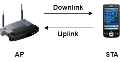
This example shows you how to model a WLAN network with UL and DL communication between an AP and a STA. This figure illustrates the example network.
This figure shows the example workflow.

To confirm compliance with the IEEE 802.11 standard [2], the features in this example are validated with Box-3 and Box-5 scenarios specified in the TGax evaluation methodology [4]. The network throughputs that are calculated for TGax simulation scenarios [5] are validated against the published calibration results from the TGax Task Group.
Configure Simulation Parameters
Set the seed for the random number generator to 1. The seed value controls the pattern of random number generation. The random number generated by the seed value impacts several processes within the simulation, including backoff counter selection at the MAC layer and predicting packet reception success at the physical layer. To improve the accuracy of your simulation results after running the simulation, you can change the seed value, run the simulation again, and average the results over multiple simulations.
rng(1,"combRecursive")Specify the simulation time in seconds. To visualize the packet communication for all of the nodes, set the enablePacketVisualization variable to true. To view the node performance visualization, set the enableNodePerformancePlot variable to true.
simulationTime =1; enablePacketVisualization =
true; enableNodePerformancePlot =
true;
Modeling full MAC at the transmitter and receiver involves performing all MAC frame operations, including complete MAC frame generation. Similarly, modeling full PHY involves complete operations related to waveform transmission and reception through a fading channel. To model the full PHY, you also need to model the full MAC. Simulating large networks with both full MAC and PHY can be computationally expensive.
When you model the full MAC with frame abstraction, the node neither generates nor decodes any frames at the MAC layer. Similarly, when modeling an abstract PHY, the node does not generate or decode any waveforms at the PHY layer. This approach enables you to reduce the complexity and runtime of system-level simulations. For more information on modeling abstract PHY, see the Physical Layer Abstraction for System-Level Simulation example.
You can switch between the different models of MAC and PHY layers by configuring the values of the MACModel and PHYModel properties of wlanNode object.
If you set the phyModel value to abstract-phy-tgax-evaluation-methodology, the PHY estimates the performance of a link with the TGax channel model by using an effective signal-to-interference-plus-noise ratio (SINR) mapping. Alternatively, if you set the phyModel value to abstract-phy-tgax-mac-calibration the PHY assumes a packet failure on interference without actually calculating the link performance. To use the full PHY, set the value of phyModel to full-phy.
macModel ="full-mac"; phyModel =
"abstract-phy-tgax-evaluation-methodology";
The example demonstrates packet capture at both AP and STA nodes. The packet capture (PCAP) or packet capture next generation (PCAPNG) file (.pcap or .pcapng, respectively) is a widely used packet capture file format to perform packet analysis. The packets are captured into a PCAP file in this example. To capture the packets exchanged during the simulation, set the capturePacketsFlag flag to true.
capturePacketsFlag =  true;
true;Configure WLAN Scenario
Initialize the wireless network simulator.
networkSimulator = wirelessNetworkSimulator.init;
Nodes
The wlanDeviceConfig object enables you to set the configuration parameters for the AP and STA. Create two WLAN device configuration objects, one for the AP and the other for the STA. Specify the operating mode, modulation and coding scheme, and transmission power (in dBm) for the AP and STA.
accessPointCfg = wlanDeviceConfig(Mode="AP",MCS=2,TransmitPower=15); % AP device configuration
stationCfg = wlanDeviceConfig(Mode="STA",MCS=2,TransmitPower=15);    % STA device configuration
To create an AP node and a STA node from the specified WLAN device configurations, use wlanNode objects. Specify the name and position of the AP and the STA. Specify the PHYModel and MACModel properties of the wlanNode object to configure the PHY and MAC models at the AP and the STA.
accessPoint = wlanNode(Name="AP", ...
    Position=[10 0 0], ...
    DeviceConfig=accessPointCfg, ...
    PHYModel=phyModel, ...
    MACModel=macModel);

station = wlanNode(Name="STA", ...
    Position=[20 0 0], ...
    DeviceConfig=stationCfg, ...
    PHYModel=phyModel, ...
    MACModel=macModel);
Create a WLAN network consisting of the AP and the STA.
nodes = [accessPoint station];
To visualize the node positions in the Cartesian plane, use the wirelessNetworkViewer object. Initialize the object with an appropriate canvas size. Add the AP and the STA to the wirelessNetworkViewer object by using the addNodes object function.
networkViewerObj = wirelessNetworkViewer(CanvasSize=[50 50 0]);
addNodes(networkViewerObj,accessPoint,Type="AP");
addNodes(networkViewerObj,station,Type="STA");

Association and Application Traffic
Associate the STA to the AP by using the associateStations object function of the wlanNode object. To configure UL and DL application traffic between the AP and STA, use the FullBufferTraffic argument of the associateStations object function.
associateStations(accessPoint,station,FullBufferTraffic="on");Wireless Channel
To model a random TGax fading channel between each node, this example uses the hSLSTGaxMultiFrequencySystemChannel helper object. Add the channel model to the wireless network simulator by using the addChannelModel object function of the wirelessNetworkSimulator object. By default, the hSLSTGaxMultiFrequencySystemChannel helper object models a stationary channel, meaning the scatterers in the environment have zero velocity.
channel = hSLSTGaxMultiFrequencySystemChannel(nodes);
addChannelModel(networkSimulator,channelFunction(channel))
Export WLAN MAC Frames to PCAP or PCAPNG File
Create a wlanPCAPWriter object to generate PCAP files. Specify the node objects at which you want to capture the packets. The object captures transmitted and received packets at each of these nodes and generates a PCAP file for each node. If you want to capture the packets in a PCAPNG file, specify FileExtension as "pcapng". Note that capturing packets is possible only when you specify the macModel value to "full-mac".
if capturePacketsFlag
    clear capturePacketsObj;                       % Clear existing object
    capturePacketsObj = wlanPCAPWriter(Node=nodes);
end
You can visualize and analyze the PCAP or PCAPNG file by using a third-party packet analyzer tool such as Wireshark.
Simulation and Results
Add the nodes to the wireless network simulator.
addNodes(networkSimulator,nodes)
To visualize the packet communication, use the wirelessTrafficViewer object. The visualization shows these plots:
Packet communication over the time and frequency domains.
State transitions of each node over time.
Add the nodes to the wirelessTrafficViewer object by using the addNodes object function.
if enablePacketVisualization
    packetVisObj = wirelessTrafficViewer;
    addNodes(packetVisObj,nodes);
end
To view the node performance, use the helperPerformanceViewer helper object.
perfViewerObj = helperPerformanceViewer(nodes,simulationTime);
Run the network simulation for the specified simulation time. The runtime visualization shows the packet communication in the time and frequency domains for the AP and the STA.
run(networkSimulator,simulationTime);


Use the plotNetworkStats object function displays these simulation plots.
MAC throughput (in Mbps) at each transmitter (AP and STA).
MAC packet loss ratio (ratio of unsuccessful data transmissions to the total data transmissions) at each transmitter (AP and STA).
Average application packet latency (in seconds) incurred at each receiver (AP and STA). The average application packet latency shows the average latency that the STA incurs to receive the DL traffic from the AP and the average latency that the AP incurs to receive UL traffic from the STA.
if enableNodePerformancePlot
plotNetworkStats(perfViewerObj);
end

Calculate the MAC throughput (in Mbps) and MAC packet loss ratio at the AP.
apThroughput = throughput(perfViewerObj,accessPoint.ID)
apThroughput =
9.3960
apPacketLossRatio = packetLossRatio(perfViewerObj,accessPoint.ID)
apPacketLossRatio =
0
Calculate the average application receive latency (in seconds) at the STA.
staAverageReceiveLatency = averageReceiveLatency(perfViewerObj,station.ID)
staAverageReceiveLatency =
0.2777
Retrieve the APP, MAC, and PHY statistics at each node by using the statistics object function of the wlanNode object. For more information about the statistics, see WLAN System-Level Simulation Statistics.
stats = statistics(nodes);
Because the wlanPCAPWriter object does not overwrite the existing PCAP or PCAPNG file, delete the object used in this simulation.
if capturePacketsFlag
    delete(capturePacketsObj);
end
Further Exploration
You can use this example to further explore these functionalities.
Configure IEEE 802.11be™ Compliant Frame Transmissions
To configure IEEE 802.11be [3] compliant frame transmissions, you can:
Specify the PHY transmission format of the WLAN device as
"EHT-SU".Specify the modulation and coding scheme (MCS) of the WLAN device as an integer in the range
[0,13].
For more information on TransmissionFormat and MCS properties, see the wlanDeviceConfig object.
Add Mobility To Nodes
You can add mobility to any node by using the addMobility object function. For more information on how to simulate a network by adding a mobility model to the node, see the Create, Configure, and Simulate Wireless Local Area Network example.
Configure Non-Stationary Channel
To simulate a non-stationary environment, configure the EnvironmentalSpeed property of the wlanTGaxChannel object to a nonzero value. In a non-stationary environment, scattering from surrounding objects, such as moving people, indoor equipment, walls, and partitions, causes the channel characteristics to fluctuate over time. As the value of EnvironmentalSpeed increases, the wireless channel experiences more rapid variations.
customisedChannel = wlanTGaxChannel(EnvironmentalSpeed=0.089);
nonStationaryChannel = hSLSTGaxMultiFrequencySystemChannel(nodes,customisedChannel);
Configure External Application Traffic
You can generate and add external application traffic such as On-Off, Video, Voice, and FTP by using the networkTrafficOnOff, networkTrafficVideoConference, networkTrafficVoIP, and networkTrafficFTP objects, respectively. For more information on how to configure, generate, and attach On-Off application traffic to the nodes, see the Simulate an 802.11ax Network with Quality of Service Parameters example.
Capture IQ Samples
Capture the IQ samples of the nodes by using the wirelessIQLogger object. For more information on how to capture IQ samples for all nodes in the simulation, see Simulate Noncollaborative Coexistence of WLAN, Bluetooth LE, and Bluetooth BR/EDR Networks example.
Appendix
This example uses these helpers:
hSLSTGaxMultiFrequencySystemChannel— Return a system channel objecthSLSTGaxAbstractSystemChannel— Return a channel object for abstracted PHY layerhSLSTGaxSystemChannel— Return a channel object for full PHY layerhSLSTGaxSystemChannelBase— Return the base channel objecthelperPerformanceViewer— Return a performance metrics viewer object
References
"IEEE Standard for Information Technology--Telecommunications and Information Exchange between Systems Local and Metropolitan Area Networks--Specific Requirements Part 11: Wireless LAN Medium Access Control (MAC) and Physical Layer (PHY) Specifications Amendment 1: Enhancements for High-Efficiency WLAN." IEEE. https://doi.org/10.1109/IEEESTD.2021.9442429.
"IEEE Standard for Information Technology--Telecommunications and Information Exchange between Systems - Local and Metropolitan Area Networks--Specific Requirements Part 11: Wireless LAN Medium Access Control (MAC) and Physical Layer (PHY) Specifications." IEEE. https://doi.org/10.1109/IEEESTD.2021.9363693.
“IEEE Standard for Information Technology–Telecommunications and Information Exchange between Systems Local and Metropolitan Area Networks–Specific Requirements - Part 11: Wireless LAN Medium Access Control (MAC) and Physical Layer (PHY) Specifications Amendment 2: Enhancements for Extremely High Throughput (EHT).” IEEE Std 802.11be-2024 (Amendment to IEEE Std 802.11-2024, as Amended by 802.11bh-2024), July 2025, 1–1020. https://doi.org/10.1109/IEEESTD.2024.11090080.
IEEE P802.11 Wireless LANs - 11ax Evaluation Methodology. IEEE 802.11-14/0571r12. IEEE, January 2016.
IEEE P802.11 Wireless LANs - TGax Simulation Scenarios. IEEE 802.11-14/0980r16. IEEE, July 2015.
See Also
Apps
- Wireless Network Modeler (Wireless Network Toolbox)
Functions
statistics|addChannelModel(Wireless Network Toolbox)
Objects
wirelessNetworkSimulator(Wireless Network Toolbox) |wirelessNetworkViewer(Wireless Network Toolbox) |wirelessTrafficViewer(Wireless Network Toolbox) |wirelessIQLogger(Wireless Network Toolbox) |networkTrafficOnOff(Wireless Network Toolbox) |networkTrafficFTP(Wireless Network Toolbox) |networkTrafficVoIP(Wireless Network Toolbox) |networkTrafficVideoConference(Wireless Network Toolbox) |wlanNode|wlanDeviceConfig|wlanTGaxChannel|wirelessNetworkEventTracer(Wireless Network Toolbox)
Topics
- Wireless Network Simulator (Wireless Network Toolbox)
- WLAN System-Level Simulation Statistics
- Plug Custom Channel into Wireless Network Simulator (Wireless Network Toolbox)
- 802.11be System-Level Simulation Using EMLSR Multilink Operation
- 802.11ax Multinode System-Level Simulation of Residential Scenario
- Explore Bluetooth LE and WLAN Coexistence in 6 GHz with LBT (Bluetooth Toolbox)