搜索
AI writes all my code now
21%
Multiple times a day
27%
A few times a week
10%
A few times a month
11%
Only for suggestions
21%
It is not allowed for my work
11%
92 个投票
I've left Matlab Answers in spring 2023. At this time the forum was full of interesting programming questions, e.g about optimizing code. A bunch of experienced Matlab users have discussed diefferent approachs and compared them. Some questions have concerned beginner problems and home work solutions, others belonged to professionally used tools for scientific work
Every week some new tools for dailiy use have been posted in the FileExchange.
Today, 3 years later, the traffic is much lower and questions concern the correct usage of Matlab commands usually. Submissions in the FileExchange are very specific and rarely useful for general programming jobs.
What has happend?
Hi everyone,
Simulations have a way of outgrowing the machine they run on (at least mine do). Bigger sweeps, longer regression suites, more data to pull in. At some point your workstation just isn't beefy enough!
I've just published a post on running larger MATLAB and Simulink simulations in the cloud (e.g. AWS): more compute when we need it, without changing how we work day to day.
The example is from automotive, but the same applies to aerospace, robotics, and beyond.
If you want to read more, here's the link: https://blogs.mathworks.com/engineering/2026/07/14/on-scaling-model-based-design-into-the-cloud/
How are others handling scaling for simulation? what's working for you?
Cheers,
George
Looking for an on-campus job next semester? We’re hiring MATLAB Student Ambassadors to host fun events, share MATLAB resources on social media, and connect with your student community.
Learn more here: https://www.mathworks.com/academia/students/student-ambassadors.html

How does everyone use MatLab right now? I can't think of any ideas what i can use this software for!
Hi everyone
It is my pleasure to be able to report on a project that several teams at MathWorks have been working on for some time now. A new object management system that promises to make object oriented code in MATLAB a lot faster.
The new system is available as a limited beta in the pre-release of MATLAB 2026b. It is not turned on by default. If you are developing OOP code, we'd love you to try it out. Most of the time, no code changes will be necessary but there are a small number of well-defined case where you will need to update your code.
The team are currently looking for MATLAB developers to work with who would like to try this out.
More details, including how to join the beta, are available in the following blog post https://blogs.mathworks.com/matlab/2026/07/14/objects-are-about-to-get-much-faster-in-matlab/
Best wishes,
Mike
MATLAB Editor (built-in editor)
74%
VS Code (Visual Studio Code)
18%
Jupyter Notebook / MATLAB Kernel
2%
PyCharm (via plugins or external )
2%
Sublime Text / Atom
1%
Others (please specify in commets)
2%
960 个投票
Hello everyone,
Does anyone know of a reliable tool (or workflow) that can automatically convert MATLAB code to C++ code? I am aware of MATLAB Coder, but I would like to know if there are any third‑party tools or scripts that can perform a similar translation, especially for numerical/computational code.
Any suggestions or experiences would be greatly appreciated. Thank you!
I follow a lot of astronomical/astrophysical missions and notice they have now gotten massive in size, scope, and data. Petabyte datasets are now commonplace. Some are now moving essentially to private clouds where researchers create accounts and use primarily FOSS tools to process data. Some examples are the Vera Rubin Observatory's Rubin Science Platform and ESA's Datalabs. Jupyter has entrenched itself deeply despite its many shortcomings. I can't create accounts on any of these platforms but I am guessing that getting support for license-servers and other paraphernalia associated with closed-source software won't be easy.
It makes sense at some level when datasets get so big they can't be practically served to a researcher's machine. But, I do wonder what this public data in private clouds means for MATLAB and similar paid software. All the projects say that FOSS encourages reproducibility but I've been burned more than once in my working life by randomly phased Python package updates and abandoned projects.
I'm retired now and don't have a dog in the fight. My MATLAB home license is just for self-improvement. I was just curious whether Mathworks and similar providers will have to give up on the basic science community and focus on applied, mission-critical areas where "some guy on Github" is not sufficient traceability.
Hi everyone,
I'm interested in learning how developers compare code, configuration files, JSON data, or text changes when working outside of version control systems.
Common scenarios include:
- Comparing two versions of a script
- Reviewing generated output
- Checking configuration changes
- Comparing API responses or JSON files
- Reviewing documentation updates
I've used IDE comparison features and online diff tools. One browser-based tool I've found useful for quick comparisons is Text Differ:
I'm curious what workflows or tools other community members prefer. Do you rely on built-in editor features, version control diffs, or dedicated comparison tools?
Looking forward to hearing your experiences.
var = yes;
86%
var=no;
6%
I don't mind either way
8%
765 个投票
<80 characters
14%
80 characters
25%
100 characters
22%
120 characters
16%
>120 characters
15%
something else (comment below)
9%
198 个投票
camelCase (variableName)
39%
PascalCase (VariableName)
12%
no capitalization (variablename)
4%
snake_case (variable_name)
27%
It varies for me
18%
802 个投票
Many widely cited code style guides originate from large-scale software engineering contexts: multi-developer teams, large codebases, separate reviewers, and tooling-driven workflows. While those constraints are valid in their domain, they often map poorly onto scientific and engineering scripting as it is typically practiced with MATLAB.
In laboratory and engineering environments, code serves a different role. It is frequently written by individuals or small groups, and then iteratively modified, copied, adapted, and extended as part of an evolving problem-solving process. In this context, the primary priorities are not strict stylistic consistency or tooling compatibility, but rather:
- maintaining clarity of underlying structure,
- minimizing the risk of errors during modification, and
- supporting rapid comprehension of mathematically or logically dense code.
This raises the question: should fixed line-length limits be replaced by context-aware principles? Could these be supported by a suitable AI tool?
The following proposal outlines a small set of heuristics governing line length, based on observations of real-world MATLAB usage, particularly for numerically intensive and structurally rich code. These heuristics aim to:
- preserve and expose meaningful structure (e.g. systems of equations, tables, repeated patterns)
- avoid formatting that obscures relationships or introduces errors, and
- treat different kinds of code (logic vs. data vs. structured expressions) appropriately.
Scope
These principles apply to scientific and engineering scripting, particularly:
- MATLAB-like environments
- numerically or structurally dense code
- monolithic or semi-monolithic workflows
- code that is frequently modified, copied, and adapted
They are not intended for large-scale commercial software engineering, where different constraints dominate.
Core Objective
Line length and formatting should maximize comprehension, structural clarity, and correctness under modification, rather than enforce arbitrary limits.
Hierarchy of Heuristics
Higher-numbered heuristics take precedence over lower-numbered ones.
1) Reasonable Line Length
Code intended for reading should use a reasonable line length, guided by:
- human visual comprehension when scanning
- clarity of expression
- preservation of logical units
This would tend toward 70-100 characters per line, depending on the density.
2) Preserve Semantic Integrity of Lines
Line breaks must not split code in ways that degrade understanding.
Avoid:
- dangling fragments
- very short continuation lines
- separation of tightly coupled elements
- etc.
Prefer:
- keeping logically cohesive expressions intact
- breaking only at clear structural boundaries
One slightly longer line is preferable to two poorly structured lines.
3) Treat Data as Data (Not Prose/Code)
Code that primarily represents data rather than logic is not intended for sequential reading.
This includes:
- large numeric vectors
- lookup tables
- pasted datasets
- etc.
Such code:
- may exceed line length limits without restriction
- should prioritize density and structural stability
- is assumed to be accessed via search or indexing rather than visual parsing
Readability is not the objective; retrievability and integrity are. Yes, this intentionally rejects the enterprise concept that data must be separate from code, instead replacing it with the concept that the IDE should support what some real-world users actually use, for example by formatting/aligning/showing data differently.
4) Preserve and Expose 2D Structure
If code encodes a logical, mathematical, or tabular structure with inherent spatial relationships, it should be represented accordingly.
This includes:
- systems of equations
- tabulated data
- repeated structured expressions
- etc.
Requirements:
- alignment should be used where it improves comprehension
- patterns should be visually apparent
- deviations from patterns should be easily detectable
This principle should be applied strongly, tending toward mandatory use where feasible.
Exception
If a structure would become impractically wide, a compromise representation may be used.
Breaking meaningful spatial structure is considered harmful to comprehension and correctness.
5) Preserve Structural Consistency Across Similar Code
Code segments representing similar or related logic should be expressed in consistent structure and layout.
This applies to:
- repeated formulas
- analogous computations
- structurally similar transformations
- etc.
Consistency enables:
- rapid comparison
- detection of inconsistencies
- safer modification
Similar logic should be represented in similar ways.
Meta-Principles
A. Structure Over Style
Line lengths should reflect the underlying structure of the problem, not conform to arbitrary limits.
B. Correctness Over Convention
Avoid line lengths and formatting that:
- obscures patterns
- hides inconsistencies
- increases the risk of modification errors
C. Optimize for Modification
Code in this domain is frequently:
- edited
- duplicated
- adapted for n
- extended
- commented-out for testing different versions
- etc
Line lengths should reduce the likelihood of errors during these operations, for example by keeping atomic concepts on the same line rather than splitting them up.
D. Anomaly Visibility
Formatting should make unexpected deviations immediately visible.
E. Tool Support
An intelligent tool should:
- respect and preserve structural layout
- avoid rigid line-length enforcement
- detect patterns and inconsistencies
- assist rather than constrain the programmer
I would be interested to hear how well these ideas match others’ experience, particularly in scientific or engineering workflows.
See also:
The problem with Trigonomety is: they do not tell you why you need to know what Cos, Sin, or Tan is, or what they are used for. It seems like a mystery, because you do not know why you need to know it, or what they are used for at all.
As of R2026a, only the Apple Silicon series is supported.
My Intel Mac dates to June 2020; the M1 series was released in November 2020.
So we got only 5 years of use before MATLAB gave up on us. 2 years (R2023b) since the native M1 version was introduced.
I don't exactly have a spare $2500 to spend on a new iMac -- especially not for one that has a maximum of 32 gigabytes of memory when my current system has 128 gigabytes of memory.
I remain disappointed that Mathworks did not continue Intel support for longer.
We are nearly at the anniversary of The Great Outage, May 19 2025 to May 27 2025. At the time, many Mathworks services were down due to a ransomware attack.
Some service was restored by May 21 2025 but it went down again after that.
I see some indication that some features such as @doc took even longer to restore than May 27th.
The outage came as MATLAB Answers usage was already declining a fair bit due to widespread AI use, and unfortunately some of the existing traffic just never came back.
Starting in R2026a you can export MATLAB figures to an HTML file that preserves axes interactions.
Click on the figure below to open the interactive MATLAB figure and pan or zoom into the axes. This demo also uses a new linkaxes feature available in R2026a.
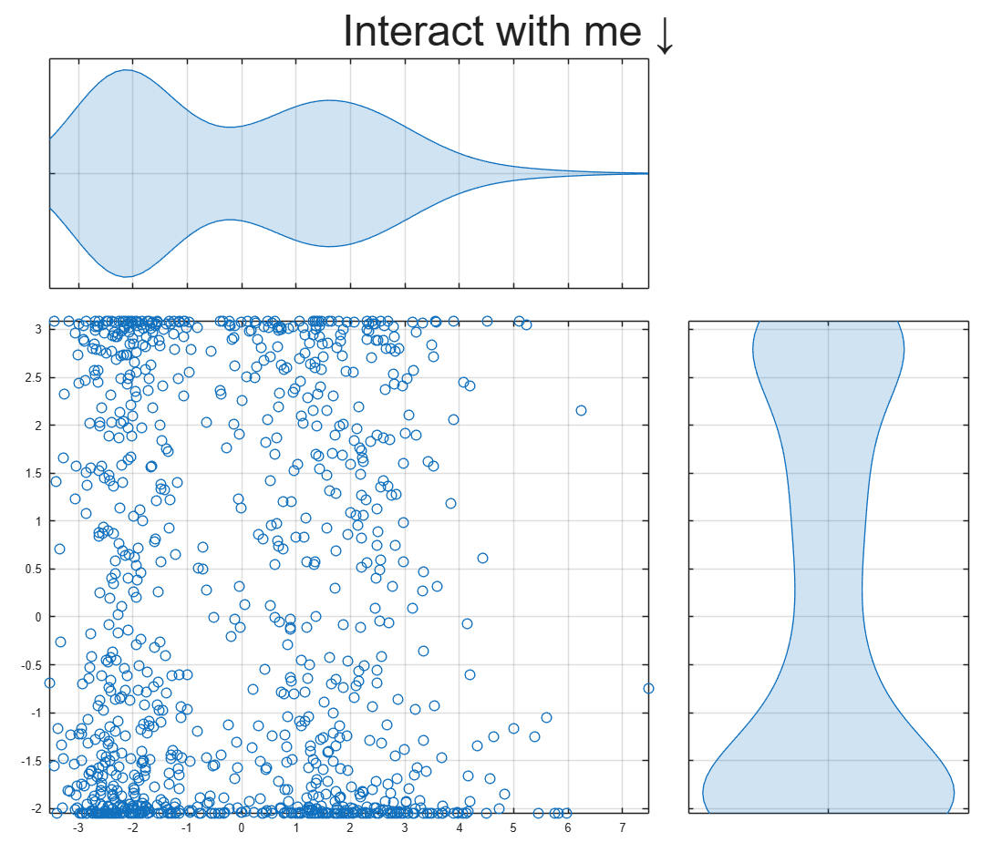
To learn about more Graphics and App Building features in R2026a, check out today's blog article:
I submitted a Matlab support case but posting this publicly to hopefully save people some trouble and see if anyone has ideas.
After upgrading my workstation from Ubuntu 25.10 to Ubuntu 26.04 LTS, MATLAB GUI consistently prints this terminal error on shutdown:
free(): chunks in smallbin corrupted
MATLAB appears to run normally, but closing the GUI takes a long time and sometimes produces crash dumps. The terminal error occurs every time I close the GUI, but crash dumps are intermittent. I attached one R2026a crash dump. I had zero issues on Ubuntu 25.10.
Affected versions:
- MATLAB R2026a
- MATLAB R2025b
- I suspect any 'new desktop' version
System:
- Ubuntu 26.04 LTS
- AMD EPYC 7443P
- NVIDIA RTX 3090
- Ubuntu 26.04 default NVIDIA driver: nvidia-driver-595-open, 595.58.03
- NVIDIA module path: /lib/modules/7.0.0-14-generic/kernel/nvidia-595-open/nvidia.ko
- glibc 2.43
Important note: the error first occurred with a clean MathWorks MATLAB installation before installing the Ubuntu/Debian `matlab-support` package. I later tested after installing `matlab-support`, which I understand modifies/renames some MATLAB-bundled libraries so MATLAB uses selected system libraries instead. The same shutdown error occurs both before and after applying `matlab-support`. This suggests the issue is not caused solely by the Debian/Ubuntu `matlab-support` integration or solely by one of the libraries it substitutes.
The attached crash dump shows abort/free() heap corruption detected in libc, but the higher-level stack includes MATLAB libraries such as:
- libmwcppmicroservices.so
- libmwmodule_descriptor_implementation.so
- libmwmatlab_main_lib.so
- libmwfoundation_threadpool.so
The issue appears GUI-specific. Using these startup flags shut down cleanly:
- matlab -batch
- matlab -nodesktop
- matlab -nodisplay
The shutdown error still occurs with these startup flags:
- normal GUI launch
- -nosplash
- -nojvm
- -softwareopengl
- -cefdisablegpu
The issue also persists after:
- renaming/resetting ~/.matlab/R2026a and ~/.MathWorks/R2026a
- launching with a clean environment without LD_LIBRARY_PATH, LD_PRELOAD, MATLAB_JAVA, JAVA_HOME, JRE_HOME, etc.
- testing a new Ubuntu user account
- testing Ubuntu/GNOME, GNOME, and Xfce X11 sessions
- testing NO_AT_BRIDGE=1 and GTK_USE_PORTAL=0
- temporarily moving ~/.MathWorks/ServiceHost
- testing GLIBC_TUNABLES=glibc.malloc.tcache_count=0
- trying to capture a system coredump with ulimit -c unlimited / coredumpctl; no system coredump was produced
Because R2025b and R2026a are both affected, terminal-only modes exit cleanly, the problem occurs across GNOME/Wayland and Xfce/X11, and the error occurred on a clean MATLAB install before any `matlab-support` modifications, this appears related to MATLAB GUI shutdown on Ubuntu 26.04 / glibc 2.43 rather than a corrupted MATLAB preference folder, a single desktop session, or the Ubuntu `matlab-support` package.
Example crash dump: