Design and PLC Implementation of Complex Industrial Control Strategies
By Parasar Kodati, MathWorks, Tom Erkkinen, MathWorks, and Arkadiy Turevskiy, MathWorks
Programmable logic controllers (PLCs) are used for control problems ranging from relatively simple, single-input single-output control loops to systems with multiple coupled loops and complex supervisory algorithms. For simple control problems, such as a single proportional-integral-derivative (PID) loop, engineers can implement a PID controller and tune gains as the machine is running. For more complex control problems, coding and verifying control logic on PLCs is much more challenging. Designers must determine the values for multiple controller parameters and make sure that all the parts of the control algorithm work together as intended. Tuning a complex controller on the hardware prototype or on the actual process is not only time-consuming; it involves considerable risk of damaging the equipment.
The solution is to use simulation to design and verify complex control strategies in a model. The same model can then be used for automatically generating IEC 61131 structured text to program PLCs for deployment. This article demonstrates this approach using a steel rolling mill system as an example.
Steel Rolling Mill System: Control Design Goals
A steel rolling mill produces a sheet of uniform thickness from a slab of steel. It typically consists of several rolling stages, with rollers in each stage compressing the sheet of steel passing through it (Figure 1). In between the roller stages, looper stages maintain the tension in the sheet and prevent tearing and formation of slack.
To simulate a multistage process, we first model and control a single rolling mill stage. The more general configuration can be analyzed by connecting several of these simpler setups.
The control system for our simple mill must meet the following requirements:
- Maintain a thickness of 8 mm +/- 0.1 mm in the produced steel at the exit of the last roller
- Maintain the required throughput to 1 m/s +/- 0.1 m/s at the exit of the last roller
- Keep the tension in the material to 1.75 N/M^2 x 10^5 after 100 secs for each roller
- Detect failures in sensors and actuators and either recover from them or safely shut down
Creating the Plant Model
We begin by creating a Simulink® model of the rolling mill that we will use to develop and test our controller. We model the process in two steps, first modeling the individual rolling stages and then the looper between them. At the rolling stage, a hydraulic actuator is used to create a roll compressive force that compresses the steel strip. The rolling torque, created by a motor drive, helps control the rolling speed. Using SimMechanics™, Simscape™, and SimHydraulics® we can model the mechanical, electrical, and hydraulic elements of the roller, respectively, without having to derive the equations explicitly.
We use SimMechanics to model the looper, representing the looper and the steel strips before and after it as three bodies connected by joints. We then combine the rolling stage and looper stage models in one Simulink system model (Figure 2).

Designing and Verifying the Controllers
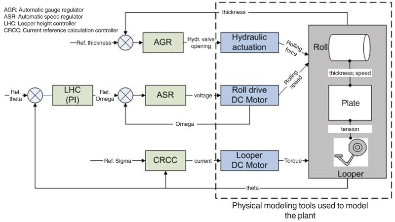
The next step is to use the plant model to design the controllers. Figure 3 shows the multiloop architecture of a typical control system for a multistage rolling mill process.
The control system consists of the following compensators:
AGR—controls the opening of the hydraulic valve to create rolling compression force to control strip thickness
ASR—commands voltage to the DC motor that creates the rolling torque and therefore controls the strip speed
LHC—sets the rotational speed reference of the rollers to indirectly achieve the desired material tension (When the tension is higher than the required value, then a higher speed setpoint is set to provide extra material to lower the tension. If the tension is lower than the required value, then the slack is removed by slowing down the sheet throughput.)
CRCC—commands current to the looper motor to position the looper to maintain material tension
Note that all loops are coupled. For example, the hydraulic actuator controlled by the AGR compensator affects not only strip thickness but also strip speed. LHC and ASR compensators work together to maintain the required tension and strip speed.
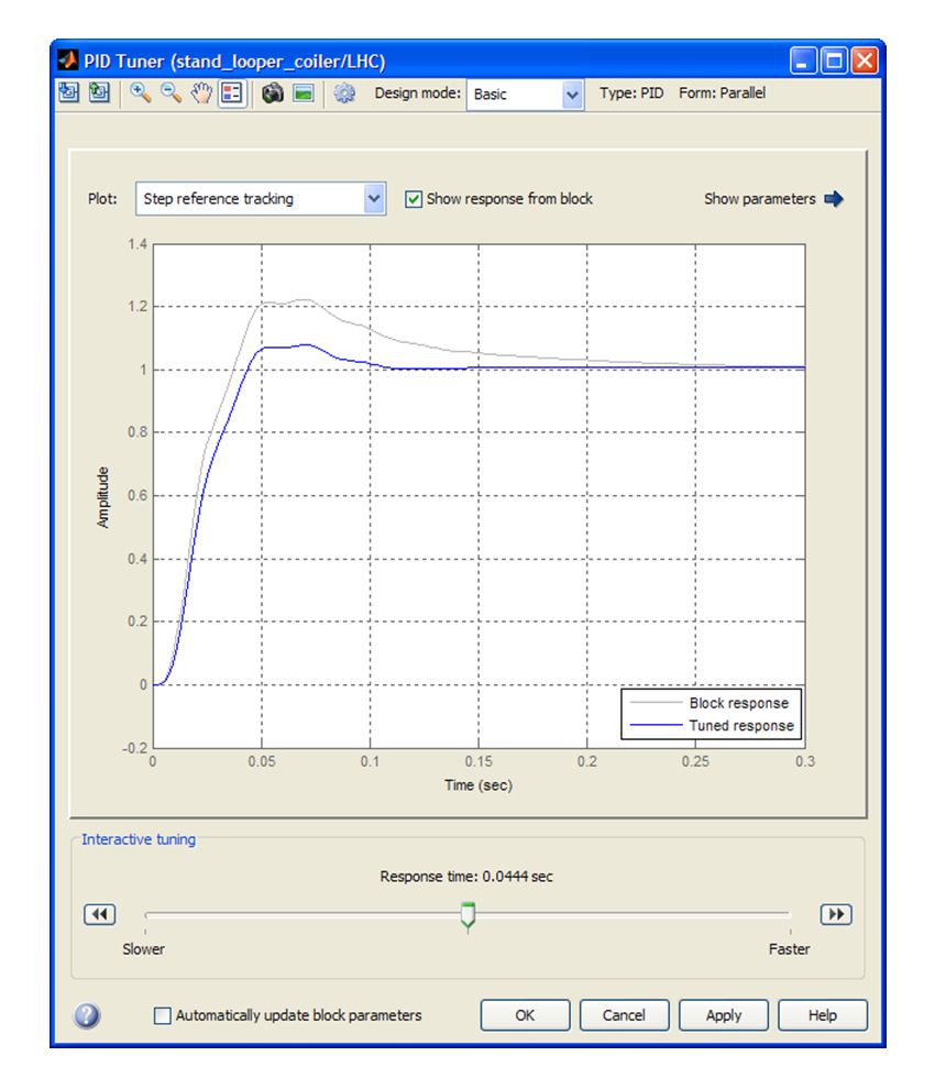
We first design compensators that control the operation of a single roller. We begin by linearizing the nonlinear model using Simulink Control Design™. We then tune the controller using the PID design tools in Simulink Control Design to compute the controller gains. The tuner (Figure 4) automatically calculates the PID gains given a desired response time. With Simulink Design Optimization™ we fine-tune the controller gains so that the system performs well in the presence of nonlinearities. The overall design is verified by running the nonlinear simulation. Note that the plant model serves two purposes: We use the linearized plant model generated by Simulink Control Design to tune our compensators, and we use the full, nonlinear plant model to verify our controller design using closed-loop simulation.
Modeling and Simulating a Multistage Process
Using custom library blocks, we reuse the rolling mill stage and the looper stage subsystems as components in the multistage process (Figure 5).
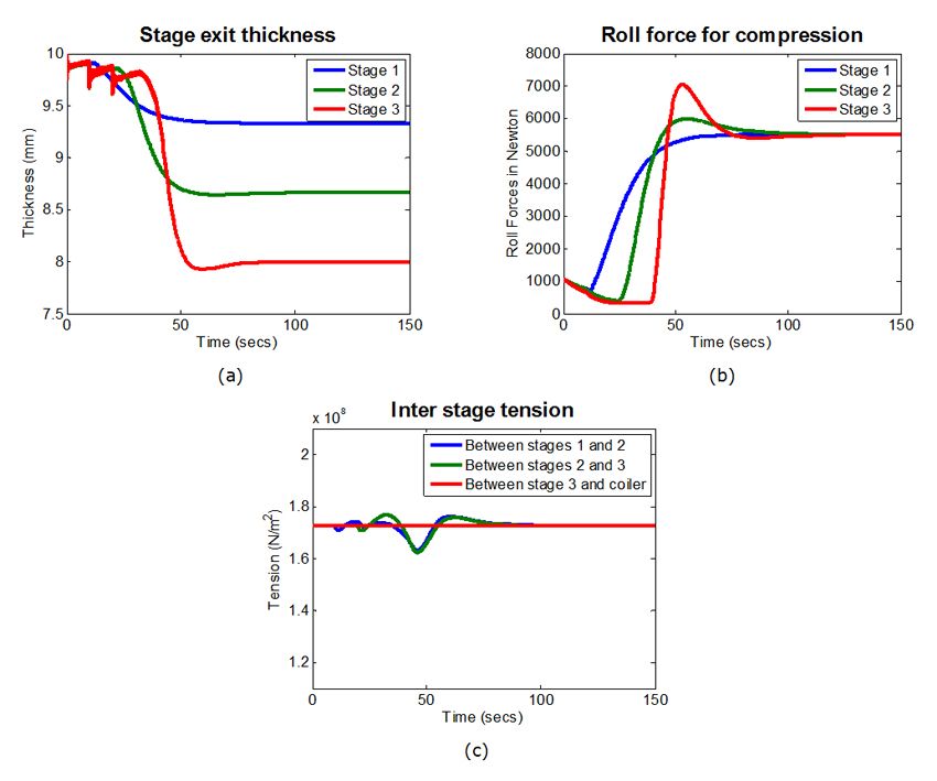
Additional subsystems are used to model other aspects of the process, such as mass conservation and transport delays across different mill stages. Figure 6 shows the process variables at each of the three stages in the process. The thickness setpoints for each stage have been achieved to produce a sheet of the thickness specified in the requirements. Disturbances in the sheet tension between the different stands have also been effectively rejected.
Designing and Verifying Fault Detection Logic
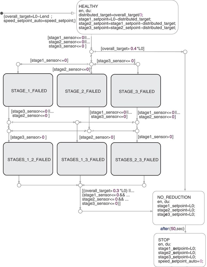
In addition to feedback compensators, process controllers must include supervisory and fault detection and recovery logic to, for example, monitor the condition of the sensors and actuators in the system. Our focus is on the fault recovery logic that detects failures in hydraulic valves and takes corrective action. Specifically, our logic will distribute the overall thickness-reduction target to individual thickness setpoints of the stages in a multistage process. When the hydraulic compression of one stage fails, the logic checks to see if the other stages can compensate for the failed stage. If they can, the thickness reduction setpoints of the working stages are recalculated to achieve the overall thickness reduction target.
We use Stateflow® to develop this logic (Figure 7). Note that this logic is a simplified representation of what would have to be developed for the actual process control because it assumes that the failed stage does not provide any compression but allows the material to pass through. In the actual setup, a much more comprehensive and complicated logic would be needed.
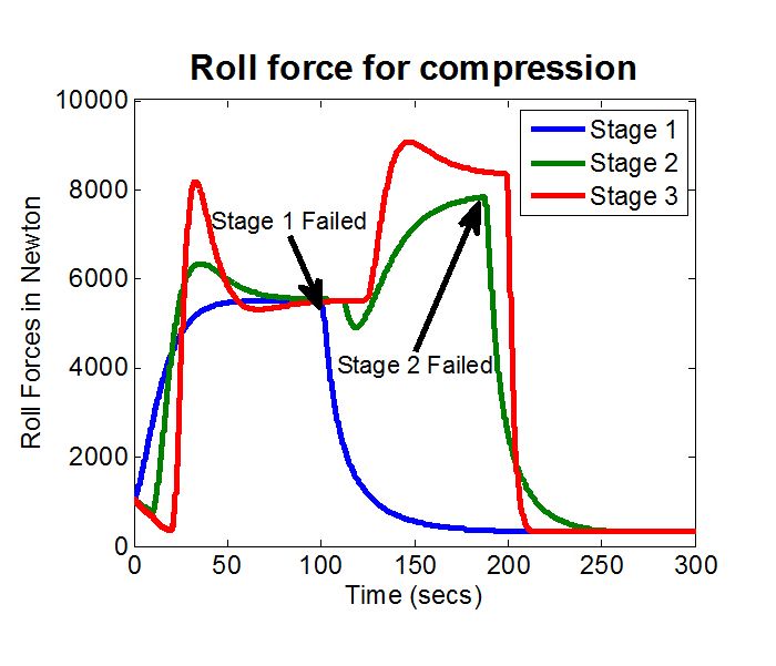
We can test the logic by artificially introducing failures into our Simulink model. Figure 8 shows the simulation results of the fault tolerance logic. When a stage fails, the supervisory controller checks to see if the load can be distributed to the remaining healthy stages. If it can, then new setpoints for thickness reduction are commanded to the individual stage AGRs. If it cannot, then the process is shut down by halting the sheet movement.
Implementing the Controller on a PLC
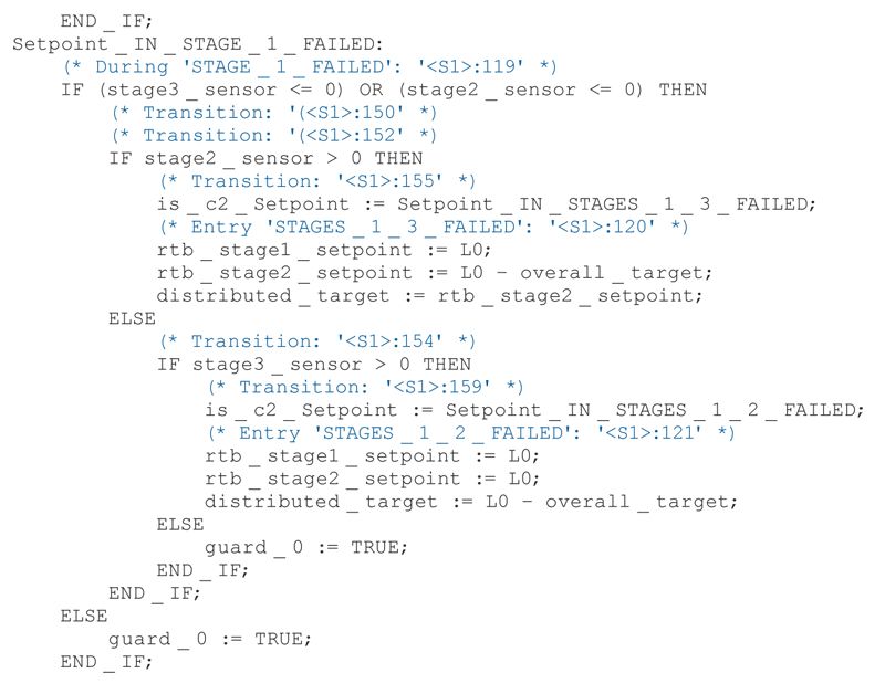
We use Simulink PLC Coder™ to automatically generate IEC 61131 structured text from our controller. This portable structured text can then be imported into the IDE used for our target PLC hardware. Figure 9 shows IEC 61131 structured text generated from the fault detection and accommodation logic. Note that the generated structured text is well commented and can be easily traced back to the model.
Automatic code generation eliminates errors that may get introduced with manual coding and helps ensure that the final structured text produces numerical results on the PLC that closely match the results we saw in simulation. Simulink PLC Coder produces a test bench that lets us compare test execution results from the IDE with the original simulation results.
If we wanted to test the fully implemented PLC hardware and software using hardware-in-the-loop testing, we could generate C code from the plant model using Simulink Coder™ and run it on a real-time simulator, such as xPC Target™, connected to the PLC control system.
Published 2011 - 91894v01

