Developing a Period-Based Air-Fuel Ratio Controller Using a Low-Cost Switching Sensor
By Peter Maloney, MathWorks
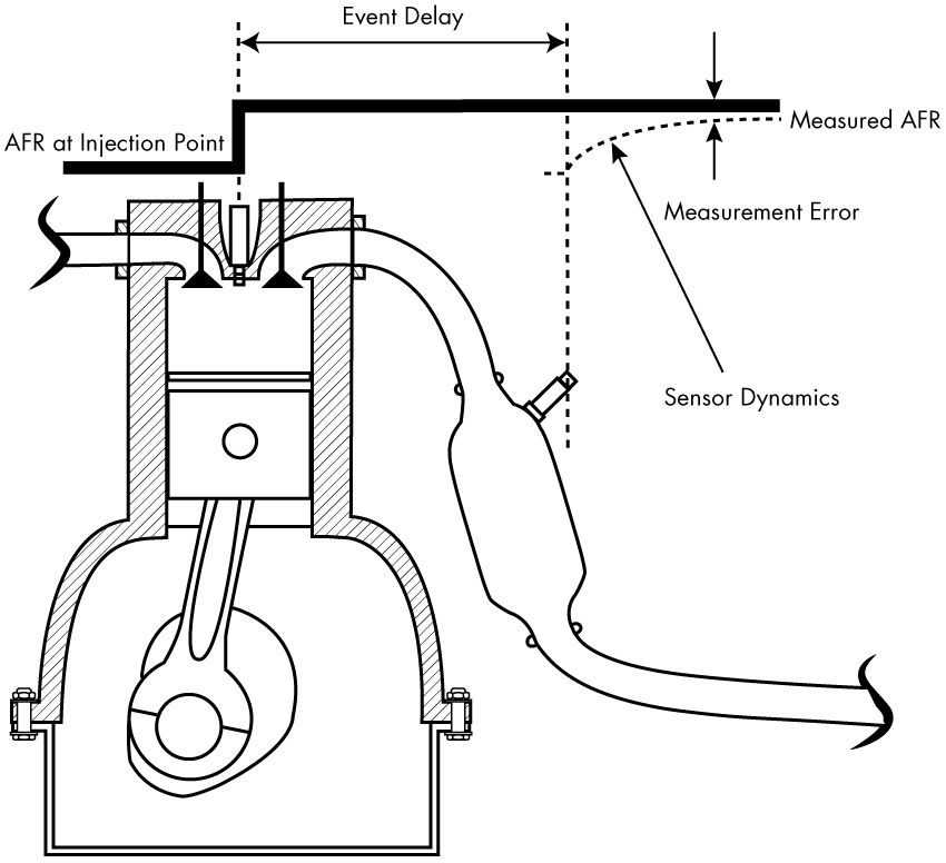
Air-fuel ratio (AFR) control is essential to improving automotive engine performance and, when used with a three-way catalytic converter (TWC), significantly reduces harmful automotive emissions. To control AFR, fuel is injected into the intake port or directly into the engine cylinder after measuring or estimating the unburned air mass in the cylinder and then correcting the injected fuel via measurements from a downstream exhaust gas oxygen sensor (Figure 1).
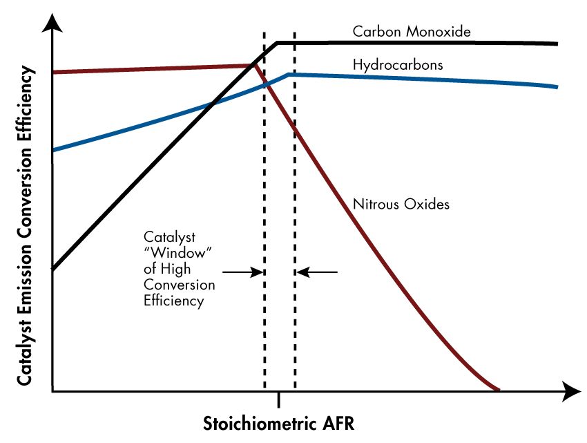
To simultaneously achieve good fuel efficiency and low exhaust emissions, a three-way catalytic converter downstream of the engine converts harmful pollutants to non-harmful emissions. Catalytic converters work most efficiently when the exhaust AFR is near the stoichiometric AFR, which is also where the air and fuel burn most completely. Around this ideal point, the AFR is said to be within the catalyst window in which the catalyst is most efficient at converting carbon monoxide, hydrocarbons, and nitrogen oxides to non-harmful exhaust products (Figure 2). Empirical studies have shown that oscillating the AFR around stoichiometry at an optimized AFR frequency, amplitude, and bias widens the catalyst window, thereby increasing catalyst conversion efficiency in the presence of unavoidable disturbances [1].
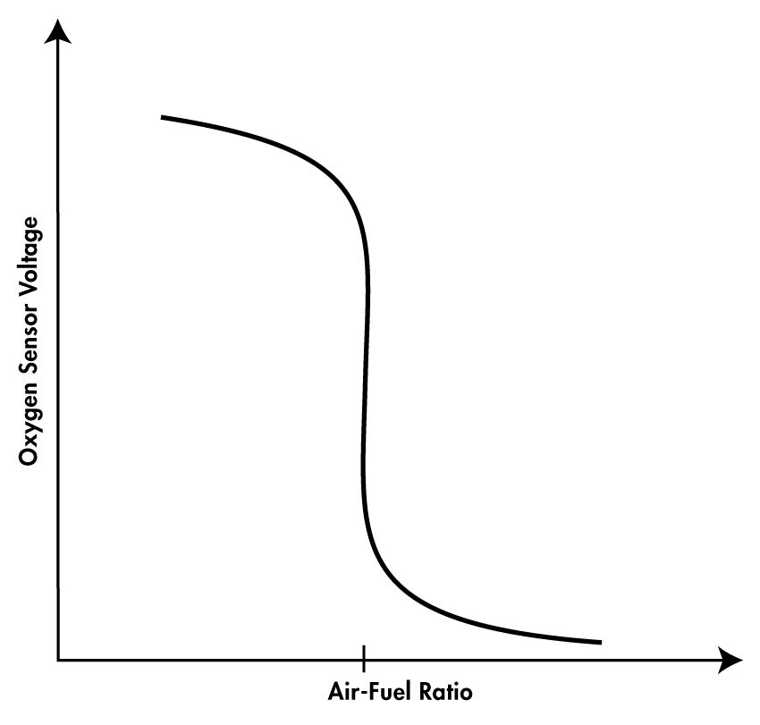
To keep production hardware costs down, automotive manufacturers design AFR control systems around inexpensive switching oxygen sensors positioned in the engine’s exhaust stream upstream and downstream of the catalyst. The oxygen sensors most commonly used in industry today have a very narrow range; essentially, they switch between lean AFR (air in excess of the stoichiometric ratio) and rich AFR (when air is less than the stoichiometric ratio) (Figure 3) [2].
Traditional proportional-integral (PI) control systems designed for these switching sensors can be difficult to calibrate. Specifically, finding the frequency, amplitude, and bias that maximize TWC efficiency is a challenge because modifying controller gains affects the frequency and amplitude of the exhaust AFR only indirectly. Further, the effects of the gain modification are difficult to assess because the transport delay—the time between changing the AFR mixture and the resulting change in the exhaust AFR—varies with the engine operating conditions.
One way to make the relationship between control gains and TWC AFR frequency and amplitude more direct is to use a wide-range oxygen sensor. Such sensors provide continuous feedback by answering the question “How rich?” or “How lean?” thereby reducing the oscillation of the traditional PI control caused by engine transport delay. Wide-range AFR sensors are often used in vehicle development, but they are generally deemed too expensive for use in mass production.
My colleagues and I designed and implemented a method for controlling AFR that combines the best of both worlds: the low cost of a conventional switching oxygen sensor and the streamlined catalyst conversion efficiency calibration made possible by direct adjustment of the exhaust AFR amplitude, frequency, and bias. This method is based on a concept presented by Meyer et al [3]. We used Model-Based Design to accelerate the design, development, and validation of the controller in Simulink® and Stateflow®. Using a combination of Simscape™ and Model-Based Calibration Toolbox™, we built an engine plant model for closed-loop simulations and then generated production code for a Pi Innovo OpenECU M220 engine controller with Embedded Coder.
Designing a Period-Based AFR Control Method
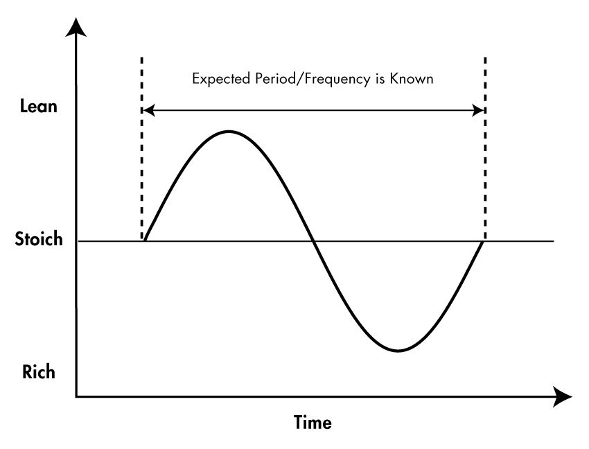
To develop a method for AFR control that combines the low cost of switching sensors with the easier AFR frequency, amplitude, and bias calibration of wide-range sensors, we started with the simple assumption that if we controlled the AFR at the injection point as a sine wave centered on the stoichiometric mixture, then the exhaust AFR would also be a sine wave. Under ideal conditions, the exhaust AFR sine wave will also be centered on the catalytic converter’s optimal AFR (Figure 4). In steady-state operation, the engine calibrator directly adjusts the AFR amplitude, frequency, and bias of the injected sinusoid so as to optimize TWC conversion efficiency. Typical frequencies, amplitudes, and biases are 0.25Hz to 1Hz, 0.25 to 1 AFR, and 0 to 0.2 AFR, respectively.
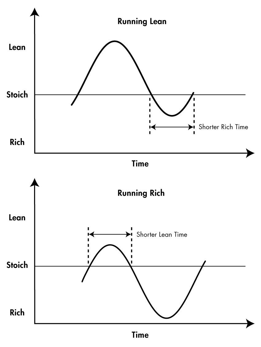
In cases where we want to run the engine at a lean AFR, the sine wave shifts up, and when we want to run the engine rich, the sine wave shifts down (Figure 5).
Under lean conditions, when the wave shifts up, the switching oxygen sensor indicates a longer lean time and a shorter rich time for each period of the sine wave. Under rich conditions, the sensor indicates a longer rich time and shorter lean time. The difference between measured lean and rich times is directly related to the richness or leanness at which the engine is running. Equations 1a and 1b define the relationship between measured AFR bias and rich and lean period measurements used to calculate the AFR controller error.
As pointed out in Meyer et al [3], the act of injecting a known AFR oscillation upstream of the engine, and then measuring whether the AFR is rich or lean based on crossing time on the exhaust side of the engine removes the need to compensate control feedback gains for unknown and variable transport delays across the engine.
\[\begin{align}C_{\text{lean}} &= \frac{\pi - \arcsin\left(\displaystyle \frac{AFR_{\text{stoich}} - AFR_{\text{cmd}}}{A_{\text{cmd}}}\right)}{2 \pi f_{\text{cmd}}\Delta t}\tag{1a}\\ C_{\text{rich}} &= \frac{1}{2 f_{\text{cmd}} \Delta t} - C_{\text{lean}}\tag{1b}\end{align}\]
Where
\(C_{\text{lean}}\) is the expected number of lean AFR sensor voltage measurement counts between stoichiometric voltage crossings
\(C_{\text{rich}}\) is the expected number of rich AFR sensor voltage measurement counts between stoichiometric voltage crossings
\(AFR_{\text{stoich}}\) is the stoichiometric air-fuel ratio for the fuel chemistry being used in the engine application
\(AFR_{\text{cmd}}\) is the expected average air-fuel ratio of the exhaust gas based on the average pulse width command delivered to the fuel injection hardware
\(A_{\text{cmd}}\) is the expected air-fuel ratio amplitude of the exhaust gas based on the amplitude of the pulse width command delivered to the fuel injection hardware
\(A_{\text{cmd}}\) is the expected air-fuel ratio frequency of the exhaust gas based on the frequency of the pulse width command delivered to the fuel injection hardware
\(\Delta t\) is the fixed time-based sample period of the oxygen sensor voltage measurement
We directly implemented the arcsine function of equation (1a) in our Pi Innovo M220 ECU. The arcsine function is not a demanding calculation in a modern floating-point ECU. With equations (1a-b) in the ECU, we can now quantify AFR in a narrow range with a switching sensor, just as if we were using a system with a wide-range sensor.
Developing an AFR Controller with Model-Based Design
To implement this new AFR control concept, we used Simulink and Stateflow to model a controller that calculates the expected lean time and rich time for a given AFR sine wave input and then produces an AFR error signal based on the difference between those times and the measured times taken from the switching oxygen sensor.
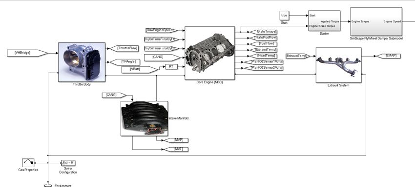
Using Simscape and Model-Based Calibration Toolbox, we built a mean-value model of the engine for use as a plant model in closed-loop simulations of the complete design (Figure 6). The plant model, which included a lookup-table submodel of the switching oxygen sensor characteristics shown in Figure 3, enabled us to rapidly iterate on our design before implementation.
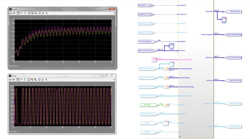
After verifying the functionality of the controller via these system-level simulations for oxygen sensor enablement and closed-loop control (Figure 7), we used Embedded Coder® to generate code for the embedded processor in the Pi Innovo M220 ECU.
Following hardware-in-the-loop tests to check real-time ECU performance, we validated the AFR control system in the engine dynamometer test cell under steady-state and dynamic conditions, followed by in-vehicle verification.
We verified on the dynamometer emission bench that the Pi Innovo M220 ECU was controlling the injection AFR to track desired mean air-fuel ratios, and that we could change the frequency, amplitude, and bias of the exhaust AFR at will. With this capability, the catalyst efficiency can be optimized directly by running sweep tests to produce a speed/load table that sets the optimal TWC AFR frequency, amplitude, and bias across engine speed and load operating points.
The period-based AFR control approach enables much faster and more straightforward catalyst efficiency calibration than the conventional approach of iteratively tuning proportional and integral gains to indirectly produce the desired frequency and amplitude.
Published 2014 - 92215v00
References
-
Heywood, John B., Internal Combustion Engine Fundamentals, McGraw-Hill, p. 656, 1988.
-
Ibid., p. 302.
-
J. Meyer, S. Yurkovich, and S. Midlam-Mohler, “Architectures for Phase Variation Compensation in AFR Control,” 2010 American Control Conference, Marriott Waterfront, Baltimore, MD, USA, June 30–July 02, 2010.
