Architecting Efficient Hardware | FPGA Design with MATLAB, Part 3
From the series: FPGA Design with MATLAB
Generating an efficient FPGA design generally involves balancing the throughput, latency, and hardware resources. Depending on the nature of your design and your goals, there are a number of ways to adapt your algorithm for efficient hardware implementation. This part of the tutorial showcases a few of the methods.
This video covers:
- Setting the model parameters for HDL code generation
- How the Simulink® model's sample rate translates to the clock rate of the FPGA hardware
- Inserting pipeline registers using various optimization techniques on the data paths
- Use of data valid control signal to monitor the input sample data
- Verification of the optimized architecture using a MATLAB® test bench
Published: 25 Sep 2019
Welcome to the HDL Coder Video Series. In this video series we will learn a popular production proven path to take a MATLAB digital signal-processing algorithm through Simulink, Fixed-Point Designer, and HDL Coder to target an FPGA.
In the first part of the video series, we discussed the strength of MATLAB and Simulink and provided an overview of the HDL Coder Self-Guided Tutorial available on the MathWorks File Exchange website. In the second video we created the Simulink model hardware implementation of the Pulse Detection Algorithm.
In this part we will prepare the Simulink model for HDL code generation and highlight techniques to optimize the hardware micro-architecture.
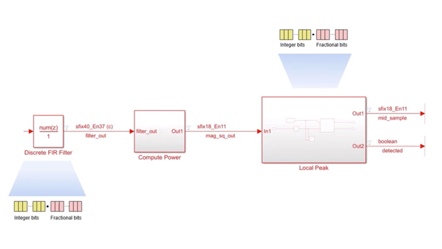
We will rename and save the model and run the HDLSETUP on the MATLAB command line. HDLSETUP configures several model parameters for HDL code generation. One of the parameters, sample time corresponds to how fast a region samples data and this is visualized by means of color code. On an FPGA, this often translates to the clock rate—how fast data gets clocked through pipeline stages, which coordinate the timing of signals as they traverse parallel paths.
Blocks with varying sample times appear in different colors when the model is updated. In our model the sample times are the same and on updating, the blocks and signal lines will appear red.
Combine the Filter block, Compute Power, and Local Peak subsystems into a top-level subsystem and name it Pulse Detector. This new subsystem will be referred to as the device-under-test, or DUT, and contains the algorithm for which we will generate HDL code.
HDL Coder software provides architecture options that extend control over speed and area tradeoffs in realization of hardware designs. We will show multiple ways of inserting pipeline stages to balance parallel paths and run at a higher clock frequency.
We will start by changing the Filter structure to Direct Form Transposed to result in better timing performance and insert additional input/output pipeline registers. Similarly, add one level of input and output pipeline registers and set “Adaptive Pipelining” to ON for the Compute Power subsystem via the HDL Block properties.
Adaptive pipelining automates the insertion of pipeline registers for certain operations, which results in improvement of the clock speed. The increase in clock speed is achieved by having less logical operations between pipeline stages. This optimization technique is dependent on the target device and frequency settings.
When we generate the HDL code from the model at the final step, we can view the delays inserted in the various blocks. The pipeline registers affect the overall simulation of the model, and to simulate the effect one can manually insert the delays.
Which is what we will do when we add a data validity check as a control signal in the Simulink model design. We create the Valid_In and Valid_out ports and add pipeline delays to the parallel paths. One on the Data Input/Output path and the other on the Valid Input/Output path present in the DUT subsystem. Log the valid_in signal after the delay block as the filter_valid signal to qualify the outputs during test.
Using the test bench script pulse_detector_v2_tb, we compare the output of the MATLAB golden reference and the updated Simulink model.
The logged filter_valid signal validates the outputs of the filter and magnitude squared blocks in the test bench script.
The output data from the test bench proves that the Simulink model after optimization for HDL code generation matches the golden reference.
In the third part of this video series on the HDL Coder, we have made changes to the Simulink model for HDL code generation and emphasized the techniques available to optimize parameters to improve speed and resource usage.
In the next video we will convert the Simulink model design to fixed-point data types.

