CDL Channel Model Customization with Ray Tracing
This example shows how to customize the CDL channel model parameters by using the output of a ray tracing analysis. The example shows how to:
Specify the location of a transmitter and a receiver in a 3D environment.
Use ray tracing to calculate the geometric aspects of the channel: number of rays, angles, delays and attenuations.
Configure the CDL channel model with the result of ray tracing analysis.
Specify the channel antenna arrays using Phased Array System Toolbox™.
Visualize the transmit and receive array radiation patterns based on singular value decomposition of a perfect channel estimate.
Base Station and UE Configuration
The example assumes that both the base station and the UE use rectangular arrays. The array orientations are specified as a pair of values representing azimuth and elevation. Both angles are in degrees.
fc = 6e9;                             % carrier frequency (Hz)
bsPosition = [22.287495, 114.140706]; % lat, lon
bsAntSize = [8 8];                    % number of rows and columns in rectangular array (base station)
bsArrayOrientation = [-30 0].';       % azimuth (0 deg is East, 90 deg is North) and elevation (positive points upwards) in deg
uePosition = [22.287323,114.140859];  % lat, lon
ueAntSize = [2 2];                    % number of rows and columns in rectangular array (UE).
ueArrayOrientation = [180 45].';      % azimuth (0 deg is East, 90 deg is North) and elevation (positive points upwards)  in deg
reflectionsOrder = 1;                 % number of reflections for ray tracing analysis (0 for LOS)

% Bandwidth configuration, required to set the channel sampling rate and for perfect channel estimation
SCS = 15; % subcarrier spacing
NRB = 52; % number of resource blocks, 10 MHz bandwidth
Import and Visualize 3-D Environment with Buildings for Ray Tracing
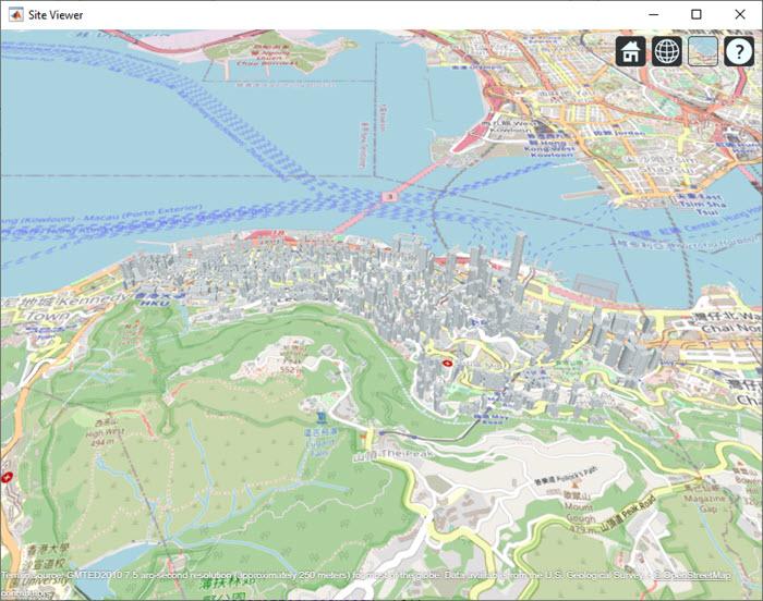
Launch Site Viewer with buildings in Hong Kong. For more information about the osm file, see [1].
if exist('viewer','var') && isvalid(viewer) % viewer handle exists and viewer window is open
    clearMap(viewer);
else
    viewer = siteviewer("Basemap","openstreetmap","Buildings","hongkong.osm");
end

Create Base Station and UE
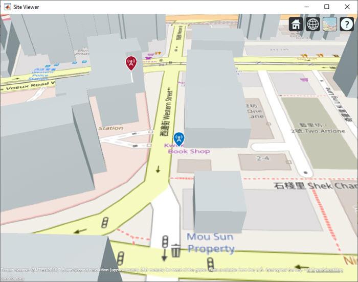
Locate the base station and the UE on the map.
bsSite = txsite("Name","Base station", ...
    "Latitude",bsPosition(1),"Longitude",bsPosition(2),...
    "AntennaAngle",bsArrayOrientation(1:2),...
    "AntennaHeight",4,...  % in m
    "TransmitterFrequency",fc);

ueSite = rxsite("Name","UE", ...
    "Latitude",uePosition(1),"Longitude",uePosition(2),...
    "AntennaHeight",1,... % in m
    "AntennaAngle",ueArrayOrientation(1:2));
Visualize the location of the base station and the UE. The base station is on top of a building.
show(bsSite);
show(ueSite);

Ray Tracing Analysis
Perform ray tracing analysis using the shooting and bouncing rays (SBR) method. The SBR method includes effects from surface reflections and diffractions but does not include effects from refraction or scattering.
pm = propagationModel("raytracing","Method","sbr","MaxNumReflections",reflectionsOrder,"MaxNumDiffractions",0);
rays = raytrace(bsSite,ueSite,pm,"Type","pathloss");
Display the rays in Site Viewer.
plot(rays{1})
From the obtained rays, get the times of arrival, the average path gains, and the angles of departure and arrival. For simplicity, normalize the propagation delay so that the first path occurs at time 0 sec, corresponding to no delay. Use the path loss to obtain the average path gains.
pathToAs = [rays{1}.PropagationDelay]-min([rays{1}.PropagationDelay]);  % Time of arrival of each ray (normalized to 0 sec)
avgPathGains  = -[rays{1}.PathLoss];                                    % Average path gains of each ray
pathAoDs = [rays{1}.AngleOfDeparture];                                  % AoD of each ray
pathAoAs = [rays{1}.AngleOfArrival];                                    % AoA of each ray
isLOS = any([rays{1}.LineOfSight]);                                     % Line of sight flag
Set Up CDL Channel Model
Configure the CDL channel model with the information generated by the ray tracing analysis. Set the DelayProfile property to 'Custom' to specify the path delays, the average path gains and the angles of arrival and departure (both in azimuth and zenith).
When configuring the channel model, take into account that:
The ray tracer finds individual rays between the base station and the UE, while the CDL channel models clusters of rays whose properties are determined by the cluster average path gain (
AveragePathGains), average angles of arrival and departure (AnglesAoA,AnglesZoA,AnglesAoD, andAnglesZoD), and the spread of the rays in the cluster (AngleSpreads). The information retrieved from the ray tracing analysis for individual rays configures the cluster average values of the CDL channel.The ray tracer performs a static analysis, while the CDL channel models UE movement. Therefore, the CDL channel introduces small-scale fading.
The path gains obtained from ray tracing are considered as average path gains. Therefore, because of fading, instantaneous channel path gains will differ from the average values, but over long simulations their mean value will match the specified average path gains when using isotropic antennas.
The CDL channel uses zenith angles, while the ray tracing analysis returns elevation angles, therefore you must convert between the two.
If any of the calculated rays is a line of sight (LOS) ray (no reflection), set the
HasLOSClusterCDL channel property totrue. For LOS cases, the CDL model splits the first path into two components, one being LOS and the other having a Rayleigh fading characteristic. This results in a combined Rician fading characteristic. Therefore, in LOS cases, when you specify N rays, the CDL channel models N+1 paths internally.
channel = nrCDLChannel;
channel.DelayProfile = 'Custom';
channel.PathDelays = pathToAs;
channel.AveragePathGains = avgPathGains;
channel.AnglesAoD = pathAoDs(1,:);       % azimuth of departure
channel.AnglesZoD = 90-pathAoDs(2,:);    % channel uses zenith angle, rays use elevation
channel.AnglesAoA = pathAoAs(1,:);       % azimuth of arrival
channel.AnglesZoA = 90-pathAoAs(2,:);    % channel uses zenith angle, rays use elevation
channel.HasLOSCluster = isLOS;
channel.CarrierFrequency = fc;
channel.NormalizeChannelOutputs = false; % do not normalize by the number of receive antennas, this would change the receive power
channel.NormalizePathGains = false;      % set to false to retain the path gains
Specify the channel antenna arrays by using Phased Array System Toolbox array objects. The array orientation properties of the CDL channel model use azimuth and downtilt while the ueArrayOrientation and bsArrayOrientation objects use azimuth and elevation. Therefore, convert the elevation to downtilt by changing the sign.
c = physconst('LightSpeed');
lambda = c/fc;

% UE array (single panel)
ueArray = phased.NRRectangularPanelArray('Size',[ueAntSize(1:2) 1 1],'Spacing', [0.5*lambda*[1 1] 1 1]);
ueArray.ElementSet = {phased.IsotropicAntennaElement};   % isotropic antenna element
channel.ReceiveAntennaArray = ueArray;
channel.ReceiveArrayOrientation = [ueArrayOrientation(1); (-1)*ueArrayOrientation(2); 0];  % the (-1) converts elevation to downtilt

% Base station array (single panel)
bsArray = phased.NRRectangularPanelArray('Size',[bsAntSize(1:2) 1 1],'Spacing', [0.5*lambda*[1 1] 1 1]);
bsArray.ElementSet = {phased.NRAntennaElement};
channel.TransmitAntennaArray = bsArray;
channel.TransmitArrayOrientation = [bsArrayOrientation(1); (-1)*bsArrayOrientation(2); 0];   % the (-1) converts elevation to downtilt
Set Channel Sampling Rate
The signal going through the channel determines the channel sampling rate. Consider a signal with subcarrier spacing of 15 kHz and 52 resource blocks (RBs), equivalent to a bandwidth of 10 MHz. To obtain the sampling rate, call the nrOFDMInfo function.
ofdmInfo = nrOFDMInfo(NRB,SCS);

channel.SampleRate = ofdmInfo.SampleRate;
Channel Estimation
For simplicity, this example assumes perfect channel estimation. Setting the ChannelFiltering property to false allows you to get the channel path gains without sending a signal through the channel.
channel.ChannelFiltering = false;
[pathGains,sampleTimes] = channel();
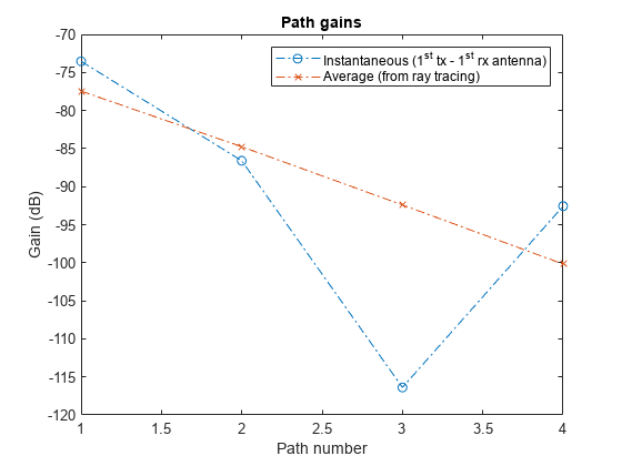
Plot the path gains returned by the channel. Compare the results with the specified average path gains obtained from the ray attenuation values.
For LOS cases, because the first two paths correspond to the first ray, the first two paths must be added together.
The CDL channel model is a statistical channel model and considers UE motion. Therefore, the returned path gains are the instantaneous gains. The path gains from the ray tracing analysis are interpreted as average path gains by the channel model.
The instantaneous path gains returned by the channel model include the gain of the antenna element in the direction of each ray. The custom path gains obtained from the ray tracing analysis do not include the antenna element gain. Therefore, in the mean, the channel path gains match the average gains only for isotropic antenna elements.
pg=permute(pathGains,[2 1 3 4]); % first dimension is the number of paths
if isLOS
    % in LOS cases sum the first to paths, they correspond to the LOS ray
    pg = [sum(pg(1:2,:,:,:)); pg(3:end,:,:,:)];
end
pg = abs(pg).^2;
plot(pow2db(pg(:,1,1,1)),'o-.');hold on
plot(avgPathGains,'x-.');hold off
legend("Instantaneous (1^{st} tx - 1^{st} rx antenna)","Average (from ray tracing)")
xlabel("Path number"); ylabel("Gain (dB)")
title('Path gains')

Obtain a perfect channel estimate for slot 0.
pathFilters = getPathFilters(channel);
nSlot = 0;
[offset,~] = nrPerfectTimingEstimate(pathGains,pathFilters);
hest = nrPerfectChannelEstimate(pathGains,pathFilters,NRB,SCS,nSlot,offset,sampleTimes);
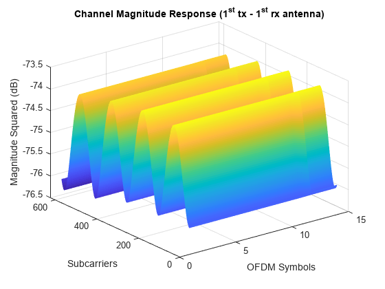
Plot the channel response in time and frequency between the first transmit and the first receive antenna. This plot shows how the channel behaves in time and frequency. For low Doppler shifts, the channel doesn't change much during the observation period of one slot.
surf(pow2db(abs(hest(:,:,1,1)).^2));
shading('flat');
xlabel('OFDM Symbols');ylabel('Subcarriers');zlabel('Magnitude Squared (dB)');
title('Channel Magnitude Response (1^{st} tx - 1^{st} rx antenna)');

Get Beamforming Weights
Calculate the beamforming weights using singular value decomposition (SVD). Assume 1 layer. The getBeamformingWeights function averages the channel conditions over a number of resource blocks, starting at an offset from the edge of the band (first subcarrier), enabling subband beamforming.
nLayers = 1;
scOffset = 0;   % no offset
noRBs = 1;      % average channel conditions over 1 RB to calculate beamforming weights
[wbs,wue,~] = getBeamformingWeights(hest,nLayers,scOffset,noRBs);
Plot Radiation Patterns
Plot the radiation patterns obtained for the UE and the base station.
% Plot UE radiation pattern
ueSite.Antenna = clone(channel.ReceiveAntennaArray); % need a clone, otherwise setting the Taper weights would affect the channel array
ueSite.Antenna.Taper = wue;
pattern(ueSite,fc,"Size",4);

% Plot BS radiation pattern
bsSite.Antenna = clone(channel.TransmitAntennaArray); % need a clone, otherwise setting the Taper weights would affect the channel array
bsSite.Antenna.Taper = wbs;
pattern(bsSite,fc,"Size",5);

References
[1] The osm file is downloaded from https://www.openstreetmap.org, which provides access to crowd-sourced map data all over the world. The data is licensed under the Open Data Commons Open Database License (ODbL), https://opendatacommons.org/licenses/odbl/.
Local Functions
function [wtx,wrx,D] = getBeamformingWeights(hEst,nLayers,scOffset,noRBs)
% Get beamforming weights given a channel matrix hEst and the number of
% layers nLayers. One set of weights is provided for the whole bandwidth.
% The beamforming weights are calculated using singular value (SVD)
% decomposition.
%
% Only part of the channel estimate is used to get the weights, this is
% indicated by an offset SCOFFSET (offset from the first subcarrier) and a
% width in RBs (NORBS).

% Average channel estimate
[~,~,R,P] = size(hEst);
scNo = scOffset+1;
hEst = hEst(scNo:scNo+(12*noRBs-1),:,:,:);
H = permute(mean(reshape(hEst,[],R,P)),[2 3 1]);

% SVD decomposition
[U,D,V] = svd(H);
wtx = V(:,1:nLayers).';
wrx = U(:,1:nLayers)';
end
See Also
Functions
Objects
nrCDLChannel|phased.URA(Phased Array System Toolbox)