nrCDLChannel
Model CDL MIMO channel
Description
The nrCDLChannel
System object™ models a clustered delay line (CDL) multiple-input multiple-output (MIMO)
link-level fading channel.
The object implements these aspects of TR 38.901 [1] and TR 38.811 [2]:
TR 38.901 Section 7.7.1: CDL models
TR 38.901 Section 7.7.3: Scaling of delays
TR 38.901 Section 7.7.5.1: Scaling of angles
TR 38.901 Section 7.7.6: K-factor for LOS channel models
TR 38.901 Section 7.6.10: Dual mobility (since R2023b)
TR 38.811 Section 6.9.1: Non-terrestrial network (NTN) CDL models (since R2026a)
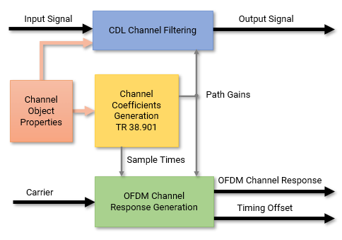
The object enables CDL channel filtering by default. When CDL channel filtering is enabled, you can send an input signal through the channel to obtain the channel-impaired signal. The default object also returns the path gains of the fading process and sample times of the channel snapshots.
The object also enables you to obtain the OFDM
channel response and timing offset when you set the ChannelResponseOutput property to 'ofdm-response'. In this
case, the object takes a carrier input, in addition to the input signal, and returns the OFDM
channel response and timing offset instead of the path gains and sample times, as shown in
this figure. (since R2024b)
To obtain channel characteristics without sending a signal through the
channel, set the ChannelFiltering property to
false.
For an overview of how the object properties configure CDL channel filtering and channel coefficients generation, see Internal Architecture of CDL Channel Model.
To debug link-level simulations with unexpected
results, you can disable channel impairments by setting the DelayProfile property to 'None'. For more information on this
channel behavior, see CDL Channel Model with Disabled Channel Impairments. (since R2026a)
To use the CDL MIMO channel model:
Create the
nrCDLChannelobject and set its properties.Call the object with arguments, as if it were a function.
To learn more about how System objects work, see What Are System Objects?
Creation
Syntax
Description
cdl = nrCDLChannel
cdl = nrCDLChannel(PropertyName=Value)DelayProfile='CDL-D' creates the channel
object with the CDL-D delay profile.
cdl = nrCDLChannel(DelayProfile='Custom',InitialDelayProfile=profile,DelaySpread=spread,KFactor=K)profile. Specify the
profile input as 'CDL-A',
'CDL-B', 'CDL-C', 'CDL-D', or
'CDL-E'. (since R2023b)
When you use this syntax:
The
DelayProfileobject property is set to'Custom'and theAnglesAoD,AnglesAoA,AnglesZoD,AnglesZoA,HasLOSCluster,KFactorFirstCluster,AngleSpreads, andXPRobject properties are set to values that are defined for the specified predefined delay profile in TR 38.901 Tables 7.7.1-1 to 7.7.1-5 [1].The values in the
PathDelaysandAveragePathGainsproperties are scaled from the initial table values to obtain the desired channel delay spread, specified byspreadin seconds, and K-factor, specified byKin dB, respectively. Specify the optionalspreadandKinputs as a numeric scalar. Thespreadinput defaults to30e-9when not specified. TheKinput defaults to the K-factor values in TR 38.901 Tables 7.7.1-4 to 7.7.1-5 (no K-factor scaling). TheKinput applies only when theprofileinput is set to'CDL-D'or'CDL-E'.
Properties
Unless otherwise indicated, properties are nontunable, which means you cannot change their
values after calling the object. Objects lock when you call them, and the
release function unlocks them.
If a property is tunable, you can change its value at any time.
For more information on changing property values, see System Design in MATLAB Using System Objects.
Delay Profile Selection
The delay profile selection determines which delay profile configuration properties are applicable to the channel.
CDL delay profile from TR 38.901 Section 7.7.1, Tables 7.7.1-1 to 7.7.1-5, and TR 38.811 Section 7.7.1, Tables 6.9.1-1 to 6.9.1-4 specified as one of these options:
'CDL-A','CDL-B','CDL-C','CDL-D','CDL-E'— To configure channel parameters that are specific to these predefined delay profiles, see the Predefined Delay Profile section.'NTN-CDL-A','NTN-CDL-B','NTN-CDL-C','NTN-CDL-D'— To configure channel parameters that are specific to these NTN predefined delay profiles from TR 38.811 Section 6.9.1, see the Predefined Delay Profile section. (since R2026a)'Custom'— To configure channel parameters that are specific to custom delay profiles, see the Custom Delay Profile section.'None'— Disable channel impairments. Use this option when simulation results, such as error vector magnitude (EVM), throughput, or block error rate (BLER), deviate from expected values and you want to isolate the root cause. For an overview of how disabling channel impairments affects the CDL channel behavior, see CDL Channel Model with Disabled Channel Impairments. (since R2026a)
Data Types: char | string
Predefined Delay Profile
These properties configure channel parameters that are specific to predefined channel
profiles, that is, when you set the DelayProfile to
'CDL-A', 'CDL-B', 'CDL-C',
'CDL-D', 'CDL-E', 'NTN-CDL-A',
'NTN-CDL-B', 'NTN-CDL-C', or
'NTN-CDL-D'.
Desired RMS delay spread in seconds, specified as a nonnegative real number. For
examples of desired RMS delay spreads,
DSdesired, see TR 38.901 Section
7.7.3 and Tables 7.7.3-1, 7.7.3-2. The default value is 30 nanoseconds.
Dependencies
To enable this property, set DelayProfile to
'CDL-A', 'CDL-B',
'CDL-C', 'CDL-D', 'CDL-E',
'NTN-CDL-A', 'NTN-CDL-B',
'NTN-CDL-C', or 'NTN-CDL-D'. This property
does not apply for custom delay profiles.
Data Types: double
K-factor scaling, specified as false or
true. When set to true, the KFactor property specifies the desired K-factor and the object applies
K-factor scaling as described in TR 38.901 Section 7.7.6.
Note
K-factor scaling modifies both the path delays and the path powers.
Dependencies
To enable this property, set DelayProfile to
'CDL-D', 'CDL-E',
'NTN-CDL-C', or 'NTN-CDL-D'.
Data Types: double
Desired K-factor for scaling in dB, specified as a numeric scalar. For typical K-factor values, see TR 38.901 Section 7.7.6 and Table 7.5-6.
Note
K-factor scaling modifies both the path delays and path powers.
K-factorapplies to the overall delay profile. Specifically, the K-factor before the scaling isKmodel, as described in TR 38.901 Section 7.7.6.Kmodelis the ratio of the power of the first path LOS to the total power of all the Laplacian clusters, including the Laplacian part of the first cluster.
Dependencies
To enable this property, set KFactorScaling to true.
Data Types: double
Apply scaling of angles, specified as false or
true according to TR 38.901 Section 7.7.5.1. When set to
true, the AngleSpreads and MeanAngles properties define the scaling of angles.
Dependencies
To enable this property, set DelayProfile to
'CDL-A', 'CDL-B',
'CDL-C', 'CDL-D', 'CDL-E',
'NTN-CDL-A', 'NTN-CDL-B',
'NTN-CDL-C', or 'NTN-CDL-D'. This property
does not apply for custom delay profiles.
Data Types: logical
Scaled mean angles in degrees, specified as a four-element row vector of the form [AoD AoA ZoD ZoA].
AoD is the mean azimuth of departure angles after scaling.
AoA is the mean azimuth of arrival angles after scaling.
ZoD is the mean zenith of departure angles after scaling.
ZoA is the mean zenith of arrival angles after scaling.
Use this vector to specify the desired mean angles of the channel used for angle scaling (), as described in TR 38.901 Section 7.7.5.1 and TR 38.811 Section 6.9.1.
Note
For 'NTN-CDL-A', 'NTN-CDL-B',
'NTN-CDL-C', and 'NTN-CDL-D' NTN delay
profiles, scaling is applied only for arrival angles.
Dependencies
To enable this property, set AngleScaling to true.
Data Types: double
Custom Delay Profile
These properties configure channel parameters that are specific to custom delay
profiles, that is, when you set the DelayProfile to
'Custom'.
Discrete path delays in seconds, specified as a numeric scalar or row vector.
AveragePathGains and PathDelays must have the same
size.
Tunable: Yes
Dependencies
To enable this property, set DelayProfile to 'Custom'.
Data Types: double
Average path gains in dB, also referred to as cluster powers in TR 38.901,
specified as a numeric scalar or row vector. AveragePathGains and
PathDelays
must have the same size. When the HasLOSCluster property is set to true, the object
splits the first element of this property into two parts, which correspond to the LOS
and NLOS parts of the first cluster. The object then uses the KFactorFirstCluster property to determine the power distribution across
the LOS and NLOS parts of the first cluster.
Tunable: Yes
Dependencies
To enable this property, set DelayProfile to 'Custom'.
Data Types: double
Azimuth of arrival angle in degrees, specified as a numeric scalar or row vector. The vector elements specify the angles for each cluster.
Tunable: Yes
Dependencies
To enable this property, set DelayProfile to 'Custom'.
Data Types: double
Azimuth of departure angle in degrees, specified as a numeric scalar or row vector. The vector elements specify the angles for each cluster.
Tunable: Yes
Dependencies
To enable this property, set DelayProfile to 'Custom'.
Data Types: double
Zenith of arrival angle in degrees, specified as a numeric scalar or row vector. The vector elements specify the angles for each cluster.
Tunable: Yes
Dependencies
To enable this property, set DelayProfile to 'Custom'.
Data Types: double
Zenith of departure angle in degrees, specified as a numeric scalar or row vector. The vector elements specify the angles for each cluster.
Tunable: Yes
Dependencies
To enable this property, set DelayProfile to 'Custom'.
Data Types: double
Line of sight (LOS) cluster of the delay profile, specified as
false or true. The PathDelays,
AveragePathGains, AnglesAoA,
AnglesAoD,
AnglesZoA,
and AnglesZoD
properties define the delay profile. To enable the LOS cluster of the delay profile,
set HasLOSCluster to true.
Dependencies
To enable this property, set DelayProfile to 'Custom'.
Data Types: logical
K-factor in the first cluster of the delay profile in dB, specified as a numeric scalar. The default value corresponds to the K-factor in the first cluster of CDL-D as defined in TR 38.901 Section 7.7.1, Table 7.7.1-4.
Dependencies
To enable this property, set DelayProfile to 'Custom' and HasLOSCluster to true.
Data Types: double
Scaled or cluster-wise root mean square (RMS) angle spreads in degrees, specified as a four-element row vector in one of these forms:
[ASD ASA ZSD ZSA] — Use this vector to specify the desired RMS angle spreads of the channel, as described in TR 38.901 Section 7.7.5.1 (ASdesired), where:
ASD is the RMS azimuth spread of departure angles.
ASA is the RMS azimuth spread of arrival angles.
ZSD is the RMS zenith spread of departure angles.
ZSA is the RMS zenith spread of arrival angles.
To use this form, set
AngleScalingtotrueandDelayProfileto'CDL-A','CDL-B','CDL-C','CDL-D', or'CDL-E'.[CASD CASA CZSD CZSA] — Use this vector to specify cluster-wise RMS angle spreads for scaling ray offset angles within a cluster, as described in TR 38.901 Section 7.7.1, Step1, where:
CASD is the cluster-wise RMS azimuth spread of departure angles.
CASA is the cluster-wise RMS azimuth spread of arrival angles.
CZSD is the cluster-wise RMS zenith spread of departure angles.
CZSA is the cluster-wise RMS zenith spread of arrival angles.
To use this form, set
DelayProfileto'Custom'. Based on TR 38.901 Section 7.7.5.1, the object does not perform angle scaling in this case.
The default value corresponds to the default cluster-wise angle spreads of CDL-A as defined in TR 38.901 Section 7.7.1 Table 7.7.1-1.
Dependencies
To enable this property, set DelayProfile to 'Custom' or AngleScaling to true.
Data Types: double
Coupling of departure and arrival rays within a cluster for azimuth and zenith, specified as one of these values:
'Random'— The object randomly couples the rays, as defined in TR 38.901 Section 7.5 Step 8, using the random number stream specified by theRandomStreamproperty.N-by-M-by-3 numeric array — Use this array to explicitly define the ray coupling. N is the number of clusters, equal to the number of path delays, specified by the
PathDelaysproperty. M is the number of rays per cluster, equal to 20. The three N-by-M planes, in the third dimension, correspond to the AoD/AoA, ZoD/ZoA, and AoD/ZoD ray couplings, respectively. Each row in each N-by-M plane specifies the ray coupling within the corresponding cluster by using a permutation of ray indices from 1 to M.Note
N is the number of clusters before any splitting into subclusters (see the
NumStrongestClustersproperty).N does not count the LOS cluster that is specified by the
HasLOSClusterproperty.
Dependencies
To enable this property, set DelayProfile to 'Custom'.
Data Types: double | char | string
Cross-polarization power ratio in dB, specified as a numeric scalar or an
N-by-M numeric matrix. N is
the number of clusters, equal to the number of path delays, specified by the PathDelays
property. M is the number of rays per cluster, equal to 20. The
default value corresponds to the cluster-wise cross-polarization power ratio of CDL-A,
as defined in TR 38.901 Section 7.7.1, Table 7.7.1-1.
Note
N is the number of clusters before any splitting into subclusters (see the
NumStrongestClustersproperty).N does not count the LOS cluster that is specified by the
HasLOSClusterproperty.
Dependencies
To enable this property, set DelayProfile to 'Custom'.
Data Types: double
Initial phases of all rays for the four polarization combinations in degrees, specified as one of these values:
'Random'— The object draws uniformly distributed random phases, as defined in TR 38.901 Section 7.5 Step 10, using the random number stream specified by theRandomStreamproperty.N-by-M-by-4 numeric array — Use this option to explicitly define the initial phases. N is the number of clusters, equal to the number of path delays, specified by the
PathDelaysproperty. M is the number of rays per cluster, equal to 20. The four N-by-M planes, in the third dimension, correspond to the θ/θ, θ/ϕ, ϕ/θ, ϕ/ϕ polarization combinations, respectively.Note
N is the number of clusters before any splitting into subclusters (see the
NumStrongestClustersproperty).N does not count the LOS cluster that is specified by the
HasLOSClusterproperty.
Tunable: Yes
Dependencies
To enable this property, set DelayProfile to 'Custom'.
Data Types: double | char | string
Number of strongest clusters to split into subclusters, specified as a nonnegative
integer. When the HasLOSCluster property is set to true, the object
splits the first cluster into the LOS and NLOS parts. If the average path gain of the
NLOS part after the split is greater than any value specified by the AveragePathGains property, the NLOS part is further split into three
subclusters. For more information, see TR 38.901 Section 7.5, Step 11.
Dependencies
To enable this property, set DelayProfile to 'Custom'.
Data Types: double
Cluster delay spread in seconds, specified as a nonnegative real number. Use this property to specify the delay offset between subclusters for clusters split into subclusters. See TR 38.901 Section 7.5, Step 11.
Dependencies
To enable this property, set DelayProfile to 'Custom' and NumStrongestClusters to a value greater than zero.
Data Types: double
Antenna Array
These properties configure geometric aspects of the channel.
Transmit antenna array characteristics, specified as a structure or a phased array
(requires Phased Array System Toolbox™). You
can retrieve the number of antennas by using the info object
function.
Phased arrays enable you to
specify different antenna array configurations, including predefined and custom antenna
elements. You can design custom antenna elements by using Phased Array System Toolbox or Antenna Toolbox™ features. To specify custom antenna elements in a 5G rectangular multipanel array,
as defined in TR 38.901 Section 7.3, use the phased.NRRectangularPanelArray (Phased Array System Toolbox) object. For an overview of phased arrays, see Array Geometries and Analysis (Phased Array System Toolbox).
When specified as a structure, this property contains the fields listed in this table.
| Parameter Field | Values | Description |
|---|---|---|
Size |
row vector |
Size of antenna array, specified as [M N P Mg Ng], where:
The overall antenna array consists of Mg-by- Ng antenna panels, where each antenna panel is of size M-by-N. If P = 1, all antenna array elements have the same polarization angle. If P = 2, half of the antenna array elements have one polarization angle and the other half have another polarization angle. The For example, this figure shows how the object maps the
input signal
|
ElementSpacing |
row vector |
Element spacing, in wavelengths, specified as a row vector of the form [λv λh dgv dgh]. The vector elements represent the vertical and horizontal element spacing and the vertical and horizontal panel spacing, respectively. The panel spacing is measured from the center of the panels. |
PolarizationAngles |
row vector |
Polarization angles in degrees, specified as a row vector of the form [θ ρ]. |
Orientation (to be
removed) |
column vector |
Note This field will be removed in a future release. Use the Mechanical orientation of the array, in degrees, specified as a column vector of the form [α; β; γ]. The vector elements specify the bearing, downtilt, and slant, respectively. The default value indicates that the broadside direction of the array points to the positive x-axis. |
Element |
|
Antenna element radiation pattern as described in TR 38.901 Section 7.3 and TR 38.811. (Note that TR 38.901 supersedes TR 38.900.) When you set
|
PolarizationModel |
|
Model that determines the radiation field patterns based on a defined radiation power pattern. For more information, see TR 38.901 Section 7.3.2. |

Mechanical orientation of the transmit antenna array, specified as a three-element numeric column vector of the form [α; β; γ]. The vector elements specify the bearing, downtilt, and slant rotation angles in degrees, respectively, as specified in TR 38.901 Section 7.1.3. The object applies these rotation angles relative to the default array orientation in the local coordinate system. For more information on how the object applies these rotation angles, see Mechanical Orientation of Antenna Arrays.
The default array orientation, corresponding to the value [0; 0;
0], depends on the TransmitAntennaArray property.
If you specify the
TransmitAntennaArrayproperty as a structure (default), in the default array orientation, the broadside direction points to the positive x-axis.If you specify the
TransmitAntennaArrayproperty as a phased array (requires Phased Array System Toolbox), you can configure the default array orientation by setting the relevant array properties of the specified phased array object.
To visualize and evaluate the resulting array orientation, call the
displayChannel function on
the channel model.
For an example of orienting transmit and receive antennas toward each other, see Orient Transmit and Receive Antennas Using LOS Path Angles.
Tunable: Yes
Dependencies
To enable this property, set DelayProfile to a
value other than 'None'.
Data Types: double
Receive antenna array characteristics, specified as a structure or a phased array
(requires Phased Array System Toolbox). You
can retrieve the number of antennas by using the info object
function.
Phased arrays enable you to
specify different antenna array configurations, including predefined and custom antenna
elements. You can design custom antenna elements by using Phased Array System Toolbox or Antenna Toolbox features. To specify custom antenna elements in a 5G rectangular multipanel array,
as defined in TR 38.901 Section 7.3, use the phased.NRRectangularPanelArray (Phased Array System Toolbox) object. For an overview of phased arrays, see Array Geometries and Analysis (Phased Array System Toolbox).
When specified as a structure, this property contains the fields listed in this table.
| Parameter Field | Values | Description |
|---|---|---|
Size |
row vector |
Size of antenna array, specified as [M N P Mg Ng], where:
The overall antenna array consists of Mg-by- Ng antenna panels, where each antenna panel is of size M-by-N. If P = 1, all antenna array elements have the same polarization angle. If P = 2, half of the antenna array elements have one polarization angle and the other half have another polarization angle. The For example, this figure shows how the object maps an
antenna array of size
|
ElementSpacing |
row vector |
Element spacing, in wavelengths, specified as a row vector of the form [λv λh dgv dgh]. The vector elements represent the vertical and horizontal element spacing and the vertical and horizontal panel spacing, respectively. The panel spacing is measured from the center of the panels. |
PolarizationAngles |
row vector |
Polarization angles in degrees, specified as a row vector of the form [θ ρ]. |
Orientation (to be
removed) |
column vector |
Note This field will be removed in a future release. Use the Mechanical orientation of the array, in degrees, specified as a column vector of the form [α; β; γ]. The vector elements specify the bearing, downtilt, and slant, respectively. The default value indicates that the broadside direction of the array points to the positive x-axis. |
Element |
|
Antenna element radiation pattern as described in TR 38.901 Section 7.3 and TR 38.811. (Note that TR 38.901 supersedes TR 38.900.) When you set
|
PolarizationModel |
|
Model that determines the radiation field patterns based on a defined radiation power pattern. For more information, see TR 38.901 Section 7.3.2. |
Mechanical orientation of the receive antenna array, specified as a three-element numeric column vector of the form [α; β; γ]. The vector elements specify the bearing, downtilt, and slant rotation angles in degrees, respectively, as specified in TR 38.901 Section 7.1.3. The object applies these rotation angles relative to the default array orientation in the local coordinate system. For more information on how the object applies these rotation angles, see Mechanical Orientation of Antenna Arrays.
The default array orientation, corresponding to the value [0; 0;
0], depends on the ReceiveAntennaArray property.
If you specify the
ReceiveAntennaArrayproperty as a structure (default), in the default array orientation, the broadside direction points to the positive x-axis.If you specify the
ReceiveAntennaArrayproperty as a phased array (requires Phased Array System Toolbox), you can configure the default array orientation by setting the relevant array properties of the specified phased array object.
To visualize and evaluate the resulting array orientation, call the
displayChannel function on
the channel model.
For an example of orienting transmit and receive antennas toward each other, see Orient Transmit and Receive Antennas Using LOS Path Angles.
Tunable: Yes
Dependencies
To enable this property, set DelayProfile to a
value other than 'None'.
Data Types: double
Carrier frequency in Hz, specified as a nonnegative real number.
Dependencies
To enable this property, set DelayProfile to a
value other than 'None'.
Data Types: double
Mobility
These properties configure how the transmitter or receiver move.
Maximum Doppler shift in Hz, specified as one of these values:
Nonnegative real number — This value specifies the maximum Doppler shift of the receiver. If the
UTDirectionOfTravelproperty is specified as a 2-by-2 matrix, this value specifies the maximum Doppler shift of the receiver as well as the transmitter.1-by-2 vector of nonnegative real numbers of the form [Rx Tx] — Rx and Tx specify the maximum Doppler shift of the receiver and transmitter, respectively. (since R2023b)
This property applies to all channel paths. When the maximum Doppler
shift is set to 0, the channel remains static for the entire input. To generate a new
channel realization, reset the object by calling the reset function.
Tunable: Yes
Dependencies
To enable this property, set DelayProfile to a
value other than 'None'.
Data Types: double
User terminal (or user equipment) direction of travel in degrees, specified as one of these values:
2-by-1 vector of real numbers of the form [RxA; RxZ] — RxA and RxZ specify the azimuth and zenith of the direction of travel of the receiver UE, respectively. If the
MaximumDopplerShiftproperty is specified as a 1-by-2 vector, RxA and RxZ specify the azimuth and zenith of the direction of travel of the receiver UE as well as the transmitter UE, respectively.2-by-2 matrix of real numbers of the form [RxA, TxA; RxZ, TxZ] — RxA and RxZ specify the azimuth and zenith of the direction of travel of the receiver UE, respectively. TxA and TxZ specify the azimuth and zenith of the direction of travel of the transmitter UE, respectively. (since R2023b)
Tunable: Yes
Dependencies
To enable this property, set DelayProfile to a
value other than 'None'.
Data Types: double
Since R2023b
Proportion of the moving scatterers in the channel, specified as a real number in
the range [0, 1]. Setting this property to 0 specifies that none of
the scatterers are moving. Setting this property to 1 specifies
that every scatterer is moving. The object selects the moving scatterers randomly
based on the RandomStream property setting. This property applies only to
dual-mobility configurations.
Dependencies
To enable this property, set DelayProfile to a
value other than 'None', and set the MaximumDopplerShift
property to a 1-by-2 vector or the UTDirectionOfTravel
property to a 2-by-2 matrix.
Data Types: double
Since R2023b
Maximum speed of the moving scatterers in the channel in m/s, specified as a nonnegative real number. This property applies only to dual-mobility configurations.
Dependencies
To enable this property, set DelayProfile to a
value other than 'None', and set the MaximumDopplerShift
property to a 1-by-2 vector or the UTDirectionOfTravel
property to a 2-by-2 matrix.
Data Types: double
Since R2026a
Path elevation angle from ground UE to satellite in degrees, specified as a numeric scalar in the range [0 90].
When you set the SatelliteElevationAngle property to a value
other than 50 degrees, the object updates the zenith angles of
arrival and zenith angles of departure of the channel.
Tunable: Yes
Dependencies
To enable this property, set the DelayProfile property to 'NTN-CDL-A',
'NTN-CDL-B', 'NTN-CDL-C', or
'NTN-CDL-D'.
Data Types: double
Channel Control
These properties configure implementation-specific parameters of the channel that are not defined by TR 38.901. For example, you can enable or disable channel filtering, set the data type and the number of samples of the filtered signal, and set control parameters for the path gain generation.
Sample rate of the input signal in Hz, specified as a positive numeric scalar.
Dependencies
To enable this property, set DelayProfile to a
value other than 'None'.
Data Types: double
Time offset of fading process in seconds, specified as a nonnegative real number.
Tunable: Yes
Dependencies
To enable this property, set DelayProfile to a
value other than 'None'.
Data Types: double
Number of time samples per half wavelength, specified as Inf or
a positive real number. The SampleDensity and MaximumDopplerShift properties control the coefficient generation
sampling rate, Fcg, given by
Fcg =
(sum(MaximumDopplerShift) + (2 ×
(MaximumScattererSpeed/lambda0)))
× 2 × SampleDensity, where
lambda0 is the carrier wavelength.
Setting SampleDensity to Inf assigns
Fcg the value of the SampleRate property.
For an example of how sample density affects the channel output and path gains, see Effect of SampleDensity Property in CDL Channel Output.
Dependencies
To enable this property, set DelayProfile to a
value other than 'None'.
Data Types: double
Source of the random number stream to initialize the ray phases and coupling using uniformly distributed random numbers, specified as one of these values:
'mt19937ar with seed'— The object uses the mt19937ar algorithm for the random number generation. Calling theresetfunction resets the filters and reinitializes the random number stream to the value of theSeedproperty. Specifying this value results in repeatable channel fading.'Global stream'— The object uses the current global random number stream for the random number generation. Calling theresetfunction resets only the filters.
Dependencies
To enable this property, set DelayProfile to a
value other than 'None', then set the RayCoupling or
InitialPhases
properties to 'Random' or configure the object with
dual-mobility. To configure dual-mobility, set the MaximumDopplerShift
property to a 1-by-2 vector or the UTDirectionOfTravel
property to a 2-by-2 matrix.
Initial seed of mt19937ar random number stream, specified as a nonnegative numeric scalar.
Dependencies
To enable this property, set DelayProfile to a
value other than 'None', and set RandomStream to 'mt19937ar with seed'. When calling
the reset function, the
seed reinitializes the mt19937ar random number stream.
Data Types: double
Normalize channel outputs, specified as true or
false. When this property is set to true, the
channel output signal is divided by the square root of the number of receive antennas.
The normalization is by NR, where
NR is the
number of receive antenna elements or the number of antenna subarrays (only when you specify the
ReceiveAntennaArray property as a phased.ReplicatedSubarray (Phased Array System Toolbox) or phased.PartitionedArray (Phased Array System Toolbox) phased array object). To determine the value of
NR, check the NumOutputSignals
structure field in the output of the info(cdl)
Note
When you call the swapTransmitAndReceive function to reverse the role of the transmit
and receive antennas within the channel, the function also swaps these output
structure fields of the
info(cdl)
NumTransmitAntennasandNumReceiveAntennasNumInputSignalsandNumOutputSignals
Therefore, the normalization is always by NR.
Data Types: logical
Normalized channel fading process, specified as true or
false. When this property is set to true, the
amplitude of the channel fading process is normalized by the average path gains (also
referred to as cluster powers in TR 38.901). This normalization does not include other
channel gains, for example, polarization and antenna element directivity. When this
property is set to false, the channel fading process is not
normalized. The DelayProfile property determines the average path gains, based on TR
38.901 Section 7.7.1, Tables 7.7.1-1 to 7.7.1-5. When you set DelayProfile to 'Custom', you can specify the average
path gains with the AveragePathGains property.
Dependencies
To enable this property, set DelayProfile to a
value other than 'None'.
Data Types: logical
Since R2024b
Channel response output, specified as one of these options:
'path-gains'— The object returns the path gains and sample times, as shown in this figure. When channel filtering is enabled, the object also returns the filtered output signal. Alternatively, to configure the channel to return only the path gains and sample times, set theChannelFilteringproperty tofalseto disable channel filtering.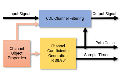
'ofdm-response'— The object returns the OFDM channel response and timing offset when you call the object with a carrier input, as shown in this figure. When channel filtering is enabled, the object also returns the filtered output signal. Alternatively, to configure the channel to return only the OFDM channel response and timing offset, set theChannelFilteringproperty tofalseto disable channel filtering.
Data Types: string | char
Fading channel filtering, specified as one of these options:
true— Enable channel filtering. The object takes an input signal to filter through the channel.false— Disable channel filtering. The object takes no input signal and returns only the OFDM channel response and timing offset (since R2024b) or the path gains and sample times, depending on theChannelResponseOutputproperty.When you disable channel filtering, these conditions apply:
The
NumTimeSamplesproperty controls the duration of the fading process realization at a sample rate given by theSampleRateproperty.The
OutputDataTypeproperty specifies the data type of the generated channel response output (OFDM channel response or path gains).
For an overview of how this property affects the internal architecture of the channel, see Internal Architecture of CDL Channel Model.
For a use case of disabling channel filtering, see the Calculate OFDM Channel Response of CDL Channel example.
Data Types: logical
Since R2026a
Enable GPU processing when channel filtering is disabled, specified as one of these values:
'off'— The object executes on the CPU.'on'— The object executes on the GPU and returns all outputs asgpuArray(Parallel Computing Toolbox) objects on the GPU.'auto'— If a GPU is available, the object automatically executes on the GPU and returns all outputs asgpuArrayobjects on the GPU. If no GPUs are available, the object executes on the CPU.
To use a GPU to accelerate computations in MATLAB®, you must have Parallel Computing Toolbox™ and a supported GPU device. For more information on supported devices, see GPU Computing Requirements (Parallel Computing Toolbox) .
Dependencies
To enable this property, set the ChannelFiltering
property to false.
Data Types: char | string
Number of time samples, specified as a positive integer. When channel filtering is disabled, you can use this property to set the duration of the fading process realization.
When you call the object with the carrier
input, carrier, set the NumTimeSamples
property to a value that is at least the number of samples in a slot. You can
calculate the number of samples in a slot from the output structure of
nrOFDMInfo(carrier). (since R2024b)
Tunable: Yes
Dependencies
To enable this property, set DelayProfile to a
value other than 'None' and set ChannelFiltering to
false.
Data Types: double
Data type of the generated channel response output, specified as
'double' or 'single'. When channel filtering
is disabled, use this property to specify the data type of the OFDM channel response (since R2024b) or path gains, depending on the ChannelResponseOutput property.
Dependencies
To enable this property, set ChannelFiltering to false.
Read-Only Properties
This property is read-only.
Reversed channel link direction, returned as one of these values:
false— The role of the transmit and receive antennas within the channel model corresponds to the original channel link direction. Calling theswapTransmitAndReceivefunction on thenrCDLChannelobject reverses the link direction of the channel and toggles this property value fromfalsetotrue.true— The role of the transmit and receive antennas within the channel model are swapped. Calling theswapTransmitAndReceivefunction on thenrCDLChannelobject restores the original link direction of the channel and toggles this property value fromtruetofalse.
Data Types: logical
Usage
Syntax
Description
Channel Filtering
OFDM Channel Response and Timing Offset
Since R2024b
To use these syntaxes, set the ChannelResponseOutput property to 'ofdm-response'.
[
applies OFDM demodulation to the channel impulse response based on the specified
carrier, signalOut,ofdmResponse] = cdl(signalIn,carrier)carrier, and returns the OFDM channel response, in
addition to the channel-impaired signal. This output shows how the channel affects each
resource element of an OFDM signal.
[
also returns the timing offset of the strongest path in the channel impulse response.
The channel impulse response is averaged across all channel snapshots and summed across
all transmit and receive antennas.signalOut,ofdmResponse,timingOffset] = cdl(signalIn,carrier)
[
returns only the OFDM channel response and timing offset without filtering an input
signal. The ofdmResponse,timingOffset] = cdl(carrier)cdl object and the carrier input act
as a source for the calculation of the OFDM channel response and timing offset. To use
this syntax, you must also set the ChannelFiltering property to false.
Path Gains and Sample Times
To use these syntaxes, set the ChannelResponseOutput property to
'path-gains' (since R2024b).
[
also returns the sample times of the channel snapshots of signalOut,pathGains,sampleTimes] = cdl(signalIn)pathGains
(first-dimension elements).
[
returns only the path gains and sample times without filtering an input signal. The
pathGains,sampleTimes] = cdl()cdl object acts as a source for the calculation of the path gains
and sample times. To use this syntax, you must also set the ChannelFiltering property to false.
Input Arguments
Output Arguments
Object Functions
To use an object function, specify the
System object as the first input argument. For
example, to release system resources of a System object named obj, use
this syntax:
release(obj)
Examples
Create a default carrier configuration object.
carrier = nrCarrierConfig;
Create a CDL channel object with the CDL-B delay profile.
channel = nrCDLChannel;
channel.DelayProfile = "CDL-B";
channel.MaximumDopplerShift = 200;
Set the sample rate of the channel to match the sample rate of the carrier.
ofdmInfo = nrOFDMInfo(carrier);
channel.SampleRate = ofdmInfo.SampleRate;
Specify the OFDM channel response as the channel output.
channel.ChannelResponseOutput = "ofdm-response";Disable channel filtering.
channel.ChannelFiltering = false;
Set the number of time samples to generate a single-slot OFDM response.
channel.NumTimeSamples = sum(ofdmInfo.SymbolLengths(1:carrier.SymbolsPerSlot));
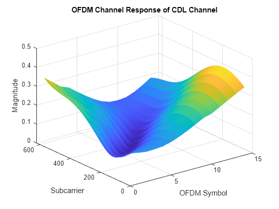
Call the CDL channel object by specifying the carrier input. The object returns the OFDM channel response and timing offset of the CDL channel.
[ofdmResponse,timingOffset] = channel(carrier);
Display the OFDM channel response.
mesh(abs(ofdmResponse(:,:,1,1)));
title('OFDM Channel Response of CDL Channel');
xlabel('OFDM Symbol'); ylabel("Subcarrier"); zlabel("Magnitude");
Transmit a waveform through a clustered delay line (CDL) channel model with delay profile CDL-D from TR 38.901 Section 7.7.1.
Define the channel configuration structure using an nrCDLChannel System object. Use delay profile CDL-D, a delay spread of 10 ns, and UE velocity of 15 km/h.
v = 15.0;                    % UE velocity in km/h
fc = 4e9;                    % carrier frequency in Hz
c = physconst('lightspeed'); % speed of light in m/s
fd = (v*1000/3600)/c*fc;     % UE max Doppler frequency in Hz

cdl = nrCDLChannel;
cdl.DelayProfile = 'CDL-D';
cdl.DelaySpread = 10e-9;
cdl.CarrierFrequency = fc;
cdl.MaximumDopplerShift = fd;
Configure the transmit array layout as a vector of the form [M N P Mg Ng] = [2 4 2 1 2], representing two panels (Mg = 1, Ng = 2) with a 2-by-4 antenna array (M = 2, N = 4) and two polarization angles (P = 2). Configure the receive antenna array as a vector of the form [M N P Mg Ng] = [1 1 2 1 1], representing a single pair of cross-polarized co-located antennas.
cdl.TransmitAntennaArray.Size = [2 4 2 1 2];
cdl.ReceiveAntennaArray.Size = [1 1 2 1 1];
Set the distance between the transmit antenna elements to half wavelength. Specify the distance between the antenna panel centers to evenly distribute the antenna elements of all panels and avoid panel overlapping.
cdl.TransmitAntennaArray.ElementSpacing(1:2) = 0.5;
cdl.TransmitAntennaArray.ElementSpacing(3:4) = cdl.TransmitAntennaArray.ElementSpacing(1:2).*(cdl.TransmitAntennaArray.Size(1:2));
Verify the configuration by displaying the channel.
displayChannel(cdl,'LinkEnd','Tx')
displayChannel(cdl,'LinkEnd','Rx')
Create a random waveform of one subframe duration with eight antennas.
SR = 15.36e6;
T = SR * 1e-3;
cdl.SampleRate = SR;
cdlinfo = info(cdl);
Nt = cdlinfo.NumInputSignals;

txWaveform = complex(randn(T,Nt),randn(T,Nt));
Transmit the input waveform through the channel.
rxWaveform = cdl(txWaveform);
Plot channel output and path gain snapshots for various sample density values while using an nrCDLChannel System object.
Configure a channel with delay profile CDL-B from TR 38.901 Section 7.7.1. Set the maximum Doppler shift to 300 Hz and the channel sampling rate to 10 kHz.
cdl = nrCDLChannel;
cdl.DelayProfile = 'CDL-B';
cdl.MaximumDopplerShift = 300.0;
cdl.SampleRate = 10e3;
cdl.Seed = 19;
Configure the transmit and receive antenna arrays for single-input/single-output (SISO) operation.
cdl.TransmitAntennaArray.Size = [1 1 1 1 1];
cdl.ReceiveAntennaArray.Size = [1 1 1 1 1];
Create an input waveform with a length of 40 samples.
T = 40;
in = ones(T,1);
Plot the step response of the channel (displayed as lines) and the corresponding path gain snapshots (displayed circles) for various values of the SampleDensity property. The sample density property controls how often the channel snapshots are taken relative to the Doppler frequency.
When
SampleDensityis set toInf, a channel snapshot is taken for every input sample.When
SampleDensityis set to a scalar S, a channel snapshot is taken at a rate of .
The nrCDLChannel object applies the channel snapshots to the input waveform by means of zero-order hold interpolation. The object takes an extra snapshot beyond the end of the input. Some of the final output samples use this extra value to minimize the interpolation error. The channel output contains a transient (and a delay) due to the filters that implement the path delays.
s = [Inf 5 2]; % sample densities

legends = {};
figure; hold on;
SR = cdl.SampleRate;
for i = 1:length(s)

    % call channel with chosen sample density
    release(cdl); cdl.SampleDensity = s(i);
    [out,pathgains,sampletimes] = cdl(in);
    chInfo = info(cdl); tau = chInfo.ChannelFilterDelay;

    % plot channel output against time
    t = cdl.InitialTime + ((0:(T-1)) - tau).' / SR;
    h = plot(t,abs(out),'o-');
    h.MarkerSize = 2;
    h.LineWidth = 1.5;
    desc = ['Sample Density = ' num2str(s(i))];
    legends = [legends ['Output, ' desc]];
    disp([desc ', Ncs = ' num2str(length(sampletimes))]);

    % plot path gains against sample times
    h2 = plot(sampletimes-tau/SR,abs(sum(pathgains,2)),'o');
    h2.Color = h.Color;
    h2.MarkerFaceColor = h.Color;
    legends = [legends ['Path Gains, ' desc]];
end
Sample Density = Inf, Ncs = 40
Sample Density = 5, Ncs = 13
Sample Density = 2, Ncs = 6
xlabel('Time (s)');
title('Channel Output and Path Gains vs. Sample Density');
ylabel('Channel Magnitude');
legend(legends,'Location','NorthWest');

Create a CDL channel model. Then specify a light-of-sight (LOS) channel.
cdl = nrCDLChannel;
cdl.DelayProfile = 'CDL-D'; % LOS channel
cdl.TransmitAntennaArray.Element = '38.901';
cdl.ReceiveAntennaArray.Element = '38.901';
Retrieve channel characteristic information. Orient the transmit and receive antenna arrays to point at each other by using the LOS path angles returned in the characteristic information.
cdlInfo = cdl.info;
cdl.TransmitArrayOrientation = [cdlInfo.AnglesAoD(1) cdlInfo.AnglesZoD(1)-90 0]';
cdl.ReceiveArrayOrientation = [cdlInfo.AnglesAoA(1) cdlInfo.AnglesZoA(1)-90 0]';
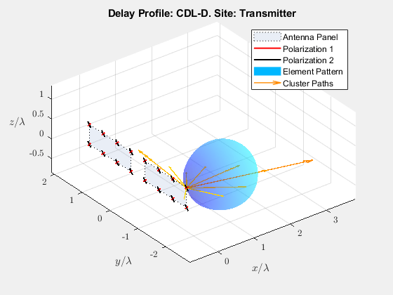
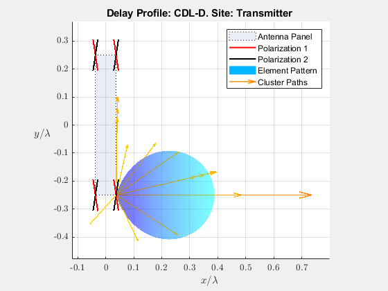
Visualize the channel characteristics at the transmitter end.
cdl.displayChannel('LinkEnd','Tx');
view(0,90)
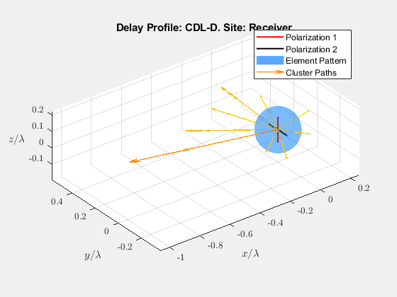
Visualize the channel characteristics at the receiver end. The strongest path (LOS) passes through the maximum of the antenna element radiation pattern, which confirms that the antennas point at each other.
cdl.displayChannel('LinkEnd','Rx')
view(0,90)

Create a CDL channel model. Then specify a phased array for the transmit antenna array.
cdl = nrCDLChannel;
cdl.TransmitAntennaArray = phased.URA;
Specify a cross-dipole transmit antenna array element to generate circularly polarized fields.
cdl.TransmitAntennaArray.Element = phased.CrossedDipoleAntennaElement;
Set the broadside direction of the array toward the positive y-axis. Add a 30 degree downtilt.
cdl.TransmitAntennaArray.ArrayNormal = 'y';
cdl.TransmitArrayOrientation = [0; 30; 0];
Set the antenna element spacing to half wavelength.
lambda = physconst('lightspeed')/cdl.CarrierFrequency;
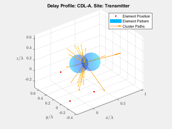
cdl.TransmitAntennaArray.ElementSpacing = [lambda/2 lambda/2];Visualize the channel characteristics at the transmitter end.
cdl.displayChannel('LinkEnd','Tx');
Create an NTN CDL channel model. Set the delay profile to 'NTN-CDL-C'.
channel = nrCDLChannel;
channel.DelayProfile = 'NTN-CDL-C';
channel.DelaySpread = 30e-9;
channel.CarrierFrequency = 2e9;
channel.SatelliteElevationAngle = 50;
Specify a Bessel antenna for the transmit antenna and receive antenna array.
channel.TransmitAntennaArray.ElementType = 'bessel';
channel.ReceiveAntennaArray.ElementType = 'bessel';
Set the antenna array size, spacing, and polarization angle.
channel.TransmitAntennaArray.Size = [1 1 1 1 1];  % 1 row, 5 columns
channel.ReceiveAntennaArray.Size = [1 1 1 1 1];
channel.TransmitAntennaArray.ElementSpacing = [0.5 0.5 0 0];
channel.ReceiveAntennaArray.ElementSpacing = [0.5 0.5 0 0];
channel.TransmitAntennaArray.PolarizationAngles = 0;
channel.ReceiveAntennaArray.PolarizationAngles = 45;
Retrieve channel characteristic information. Orient the transmit and receive antenna arrays to point at each other by using the LOS path angles returned in the characteristic information.
channelInfo = channel.info;
channel.TransmitArrayOrientation = [channelInfo.AnglesAoD(1) channelInfo.AnglesZoD(1)-90 0]';
channel.ReceiveArrayOrientation = [channelInfo.AnglesAoA(1) channelInfo.AnglesZoA(1)-90 0]';
Generate a waveform and pass this waveform through the configured channel.
txWaveform = randn(1000, prod(channel.TransmitAntennaArray.Size));
rxWaveform = channel(txWaveform);
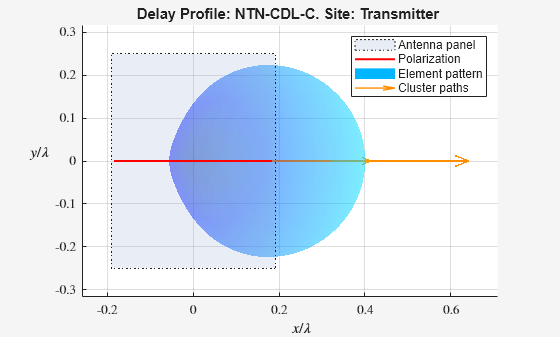
Visualize the channel characteristics at the transmitter end.
displayChannel(channel,'LinkEnd','Tx')
view(0,90)
Algorithms
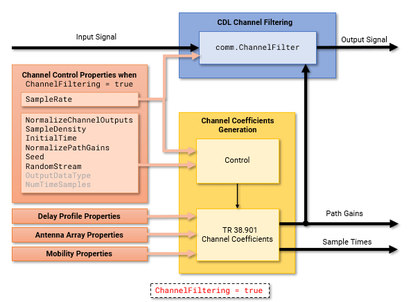
The object properties configure the CDL channel filtering and channel coefficients generation.
To enable or disable CDL channel filtering, use the ChannelFiltering property.
CDL Channel Filtering Enabled — When you set
ChannelFilteringtotrue, the object accepts an input signal and returns the channel-impaired signal. Depending on theChannelResponseOutputproperty, the object returns also the:OFDM channel response and timing offset (when
ChannelResponseOutput='ofdm-response'). (since R2024b)Path gains and sample times (when
ChannelResponseOutput='path-gains').
This figure shows the internal architecture of the CDL channel model when channel filtering is enabled and the object returns the OFDM channel response and timing offset. (since R2024b)
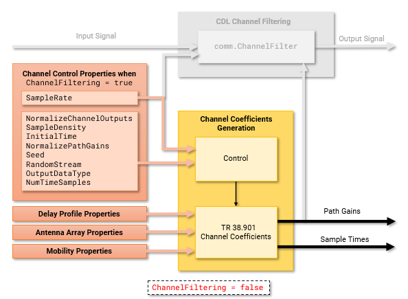
CDL Channel Filtering Disabled — When you set
ChannelFilteringtofalse, the object does not accept an input signal. However, depending on theChannelResponseOutputproperty, the object returns the:OFDM channel response and timing offset (when
ChannelResponseOutput='ofdm-response'). (since R2024b)Path gains and sample times (when
ChannelResponseOutput='path-gains').
Use the
OutputDataTypeandNumTimeSamplesproperties to set the channel response output data type and the duration of the fading process realization, respectively.This figure shows the internal architecture of the CDL channel model when channel filtering is disabled and the object returns only the OFDM channel response and timing offset. (since R2024b)
To configure TR 38.901-specific parameters:
Set the delay profile,
DelayProfile, then configure delay-profile-specific parameters. Depending on the delay profile, use the properties listed in the Predefined Delay Profile or Custom Delay Profile sections.Configure the channel geometry by using the properties listed in the Antenna Array section.
Configure the UE mobility by using the properties listed in the Mobility section.
To configure non-TR 38.901-specific implementation details of the coefficients generation, use the properties listed in the Channel Control section.
References
[1] 3GPP TR 38.901. “Study on channel model for frequencies from 0.5 to 100 GHz.” 3rd Generation Partnership Project; Technical Specification Group Radio Access Network.
[2] 3GPP TR 38.811. “Study on New Radio (NR) to support non-terrestrial networks.” 3rd Generation Partnership Project; Technical Specification Group Radio Access Network.