Test AI-based CSI Compression Techniques for Enhanced PDSCH Throughput
This example demonstrates the measurement of physical downlink shared channel (PDSCH) throughput in a 5G New Radio (NR) system, with a primary focus on AI-based compression methods for channel state information (CSI) feedback. AI for wireless is increasingly important in the evolution of 5G and emerging 6G technologies, enabling intelligent adaptation, efficient resource allocation, and enhanced network performance through data-driven methods. This area of study has received significant attention from 3GPP. Specifically, TR 38.843 which focuses on the study of using AI and Machine Learning (ML) for physical layer procedures, including efficient CSI feedback mechanisms.
The example uses CSI feedback to dynamically adapt transmission parameters such as code rate, modulation, number of layers, and MIMO precoding matrix. The model compares standard and AI-driven CSI compression techniques to assess their impact on throughput performance. Additionally, this example highlights MATLAB® and PyTorch® co-execution, showcasing how AI models developed in PyTorch can be seamlessly integrated into MATLAB-based wireless system simulations. In this example you:
Configure simulation parameters including channel, carrier, PDSCH and CSI Reference Signals (CSI-RS).
Select and load AI-based CSI Compression method.
Perform PDSCH simulation by integrating selected AI-based CSI Compression technique and measure throughput.
Compare throughput of PDSCH Simulation with conventional methods.
Simulation Workflow
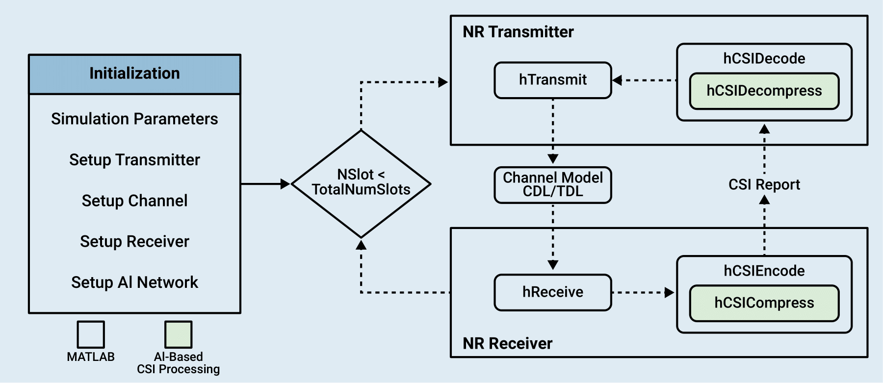
The figure shows the steps of PDSCH throughput measurement in this simulation with an emphasis on using AI-based compression methods for CSI feedback from the user equipment (UE) to adjust the transmission parameters. This example highlights AI-based CSI compression methods and enables a comparative analysis of throughput performance against conventional CSI feedback mechanisms.
The UE uses CSI-RS to estimate downlink channel response. An AI-based model compresses the channel estimate and the UE sends the CSI feedback to the gNodeB. In gNodeB, the channel estimate is decompressed and used to configure the target code rate, modulation, number of layers, and MIMO precoding matrix in subsequent PDSCH transmissions after a configurable delay. For more information on the PDSCH simulation setup with conventional CSI Feedback method, refer to the NR PDSCH Throughput Using Channel State Information Feedback example.
The simulation assumes these conditions for all forms of CSI feedback:
No uplink transmissions. The CSI feedback is transmitted without errors from the UE to the gNodeB.
Fixed PDSCH PRB allocation for the duration of the simulation. No scheduler exists to adapt the allocation to the channel conditions.
Frequency division duplexing operation.
No hybrid automatic repeat-request support.
Configure Simulation Parameters
The hConfigSimulationParameters function configures all the necessary parameters related to carrier, channel, PDSCH, CSI-RS, transmitter antennas, and receiver antennas. For more details on how to configure these parameters, refer to NR PDSCH Throughput Using Channel State Information Feedback example.
simParameters = hConfigSimulationParameters();
Simulation Length and SNR Points
Set the length of the simulation in terms of the number of 10 ms frames. To produce statistically meaningful throughput results, you must update the number of frames (NFrames) to a large number. Set the signal-to-noise ratio (SNR) points to simulate. The SNR for each layer is defined per resource element (RE) and includes the effect of signal and noise across all antennas. For an explanation of the SNR definition that this example uses, see the SNR Definition Used in Link Simulations example.
simParameters.NFrames = 2;      % Number of 10 ms frames
simParameters.SNRIn = [-10 10]; % SNR range (dB)
Simulation Diagnostics
The variable verbose controls the display of simulation information.
verbose =  true;
true;CSI Feedback Network Configuration
Specify the CSI feedback mode from the available options. Choose 'CSINet - MATLAB' or 'CLNet - PyTorch' for AI-based compression, or select 'Type 1 Single Panel' to use the conventional CSI feedback method. The UE compresses channel estimates using an AI neural network autoencoder and reports them to the gNodeB periodically. The gNodeB recovers the channel estimates by using the decoder section of autoencoder and selects appropriate target code rate, modulation, number of layers, and MIMO precoding matrix. The gNodeB applies the selected configuration in a subsequent PDSCH transmission after a configurable delay. You can specify the filename of the neural network.
CSINet - MATLAB: Uses the trained network from the MATLAB®-based Train Autoencoders for CSI Feedback Compression example.
CLNet - PyTorch: Uses the trained network from the PyTorch®-based Offline Training and Testing of PyTorch Model for CSI Feedback Compression example.
Type 1 Single Panel: Uses the 'RI-PMI-CQI' method of CSI reporting based on TS 38.214 Section 5.2.2 with codebook type as '
Type1SinglePanel' from the NR PDSCH Throughput Using Channel State Information Feedback example.
The neural networks training does not include channel aging effects. For different configurations of transmit antennas, grid size, subcarrier spacing, and other parameters, you need to retrain the neural network as per the mentioned examples. The figure below depicts the initialization process for loading either a MATLAB or PyTorch-based model for the configuration selected.
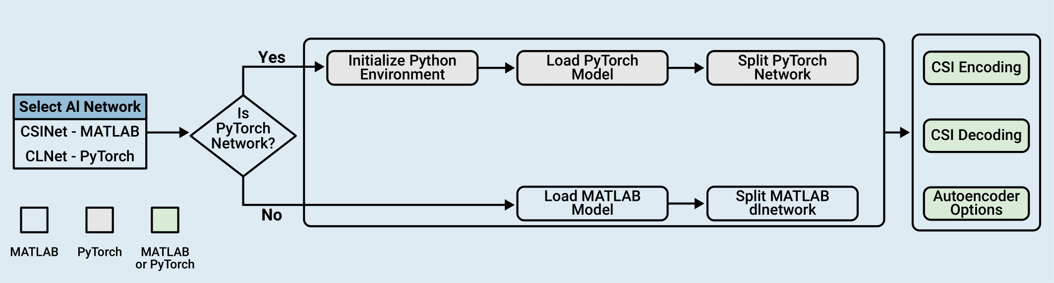
Select the AI-based CSI compression neural network from the dropdown.
csiReportMode = "CSINet";
simParameters.CSIReportMode{csiReportMode} = true;
"CSINet";
simParameters.CSIReportMode{csiReportMode} = true;Specify the CSI report configuration.
simParameters.CSIReportConfig = struct();
simParameters.CSIReportConfig.Period = [5 0];  % Periodicity and offset of the CSI report in slots

if simParameters.CSIReportMode{"CSINet"}                          % CSINet
    % Specify the file name of the AI neural network
    simParameters.AINetworkFilename = 'csiTrainedNetwork202512.mat';
elseif simParameters.CSIReportMode{"CLNet - PyTorch"}             % CLNet - PyTorch
    % Specify the file name of the AI neural network
    simParameters.AINetworkFilename = fullfile("savedModels","CLNet16.pt");
elseif simParameters.CSIReportMode{'Type1SinglePanel'}
    % Load CSI report config for codebook based CSI Feedback
    simParameters.CSIReportConfig = hLoadCSIReportConfig(simParameters);
end
Configure the CSI processing delay in slots. For the UE, this delay is the number of time slots between the reception of the CSI-RS and the availability of the CSI feedback. For the gNodeB, the delay is the number of time slots between the reception of the CSI report and the downlink transmission using the recommended CSI.
simParameters.UEProcessingDelay = 7;
simParameters.BSProcessingDelay = 1;
Setup Python Environment
If 'CLNet - PyTorch' is selected for csiReportMode, select a Python® environment as described in Call Python from MATLAB for Wireless before running the example. Specify the full path of the Python executable to use below. The helperSetupPyenv function sets the Python Environment in MATLAB based on the selected options and checks that the libraries listed in the requirements_csi_feedback.txt file are installed.
If you use Windows®, provide the path to the pythonw.exe file.
if simParameters.CSIReportMode{'CLNet - PyTorch'} if ispc simParameters.ExePath = ".venv\Scripts\pythonw.exe"; else simParameters.ExePath = "../python/python/bin/python3"; end simParameters.ExeMode ="OutOfProcess"; end
Load AI Network
This section prepares the neural network components required for the CSI feedback loop. The getCSIFeedbackOptions helper function returns the csiFeedbackOpts structure containing feedback configuration information from the main simulation parameters. The hLoadAINetwork function uses the csiFeedbackOpts structure to load the pre-trained encoder and decoder models selected. (either the MATLAB-based dlnetwork object or the PyTorch-based model). Finally, the loaded models and their specific options (such as input and output tensor sizes) are consolidated into the csiParams structure, which serves as the central configuration object for the subsequent throughput simulation.
if simParameters.CSIReportMode{"CSINet"} || simParameters.CSIReportMode{"CLNet - PyTorch"}
    csiFeedbackOpts = getCSIFeedbackOptions(simParameters);
    [csiEncoder,csiDecoder,~,autoEncOptions] = hLoadAINetwork(csiFeedbackOpts);
    % CSI Parameters
    csiParams.csiFeedbackOpts = csiFeedbackOpts;
    csiParams.csiEncoder = csiEncoder;
    csiParams.csiDecoder = csiDecoder;
    csiParams.autoEncOptions = autoEncOptions;
    csiParams.csirsCDMLengths = simParameters.csirsCDMLengths;
elseif simParameters.CSIReportMode{'Type1SinglePanel'}
    csiFeedbackOpts = getCSIFeedbackOptions(simParameters);
    csiParams.csiFeedbackOpts = csiFeedbackOpts;
end
Integrate AI-Based CSI Feedback into PDSCH
This example is designed with a modular interface that enables you to integrate and test your own custom AI compression and decompression models by modifying the hCSICompress and hCSIDecompress functions. This figure illustrates the integration of AI-based CSI feedback within the 5G NR physical layer processing chain.
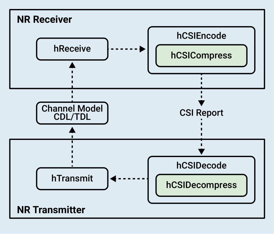
The integration consists of receiver, CSI feedback, transmitter and channel components.
NR Receiver: The
hReceivefunction encapsulates the UE receiver operations, including timing synchronization, OFDM demodulation, and channel estimation, which provides the estimated channel matrix required for CSI feedback calculation.CSI Feedback:
CSI Encoding: At the NR Receiver (UE), the
hCSIEncodefunction processes the estimated channel matrix to generate a CSI report containing feedback for the transmitter.For the conventional method, the report includes standard metrics such as Rank Indicator (RI), Precoding Matrix Indicator (PMI), and Channel Quality Indicator (CQI).
For the AI-based workflow, the function calls
hCSICompress(highlighted in green) to utilize an AI compression model, mapping the high-dimensional channel matrix into a compressed array (codeword). The compressed representation is then packaged into thecsiReportstructure for efficient transmission to the gNodeB. ThehCSICompressfunction takes an AI compression model, channel matrix and model options structure as input and provides compressed representation of channel matrix as output.
CSI Decoding: The NR Transmitter (gNodeB) uses the
hCSIDecodefunction to process the received CSI report and derive transmission parameters.For the conventional method, the function directly utilizes the Rank Indicator (RI), Precoding Matrix Indicator (PMI), and Channel Quality Indicator (CQI) from the report to configure the precoding weights and transmission parameters.
For the AI-based workflow, the function calls
hCSIDecompress(highlighted in green) to reconstruct the channel estimate from the compressed codeword using an AI decompression model. The reconstructed channel matrix is then used to calculate the necessary precoding weights and transmission parameters for subsequent downlink slots. Similar to above, thehCSIDecompressfunction takes an AI decompression model, compressed codeword, and model options structure as input and provides reconstructed channel matrix as output.
Hcis the compressed channel estimate output fromhCSICompress.H_hatis the reconstruction of the channel matrixH.
% Compress channel estimates using an AI network
Hc = hCSICompress(csiEncoder,H,autoEncOptions);

% Decompress CSI report using AI network
H_hat = hCSIDecompress(csiDecoder,Hc,autoEncOptions);
NR Transmitter: The
hTransmitfunction includes the gNodeB transmitter operations, applying the precoding weights derived from the decompressed CSI report to the PDSCH and DM-RS signals before OFDM modulation.Channel Model: The simulation utilizes a Clustered Delay Line (CDL) or Tapped Delay Line (TDL) channel model to introduce realistic propagation effects, such as multipath fading and delay spread, between the transmitter and receiver. The simulation also incorporates channel aging to capture the time-varying nature of the link.
% Receiver function
[rxOutput,csiParams] = hReceive(rxWaveform,perfectChannelInfo,carrier, ...
                                    decodeDLSCH,simParameters.PerfectChannelEstimator, ...
                                    pdschParams,maxChDelay,wtx,noiseEst, ...
                                    txOutput.trBlkSizes,csiParams);

% Compress channel estimate and create CSI report
rxCSIReport = hCSIEncode(carrier,rxOutput.Hest,noiseEst,csiParams);
[csiParams,csiReports] = storeCSIReport(rxCSIReport,csiReports,csiParams,nslot,simParameters);
% Reconstruct channel estimate and update precoding weights
[pdschParams,wtx] = hCSIDecode(carrier,pdschParams,csiReports(reportIndex),csiParams);

% Transmitter function
[txOutput,pdschParams,encodeDLSCH,decodeDLSCH,...
    csiParams] = hTransmit(carrier,csiParams,pdschParams,encodeDLSCH,decodeDLSCH,wtx,reportIndex);

% Channel function
[rxInput] = hChannel(txOutput,channel,carrier,maxChDelay,N0);
This workflow allows you to swap between AI models - implemented in either MATLAB or PyTorch - in a standard simulation loop. For more details on NR PDSCH Simulation, see the NR PDSCH Throughput Using Channel State Information Feedback example.
Measure PDSCH Throughput
The hThroughputSimulation performs PDSCH simulation based on configured simulation length and SNR points. Simulation takes around ~4 hours for 100000 slots (NFrame = 10000, SNRIn = 10dB) on an AMD® EPYC™ 7313 CPU @3.7GHz with NVIDIA® RTX A5000 GPU.
simResults = hThroughputSimulation(simParameters,csiParams,displaySimulationInformation = verbose);
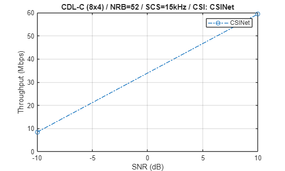
Simulating transmission scheme 1 (8x4) and SCS=15kHz with CDL-C channel at -10dB SNR for 2 10ms frame(s)
Using compressed channel estimates as CSI feedback.

( 5.00%) NSlot= 0: Transmission succeeded (Layers=1, Mod=16QAM, TCR=0.479, CR=0.462). Using initial CSI. CSI-RS transmission.
(10.00%) NSlot= 1: Transmission succeeded (Layers=1, Mod=16QAM, TCR=0.479, CR=0.423).
(15.00%) NSlot= 2: Transmission succeeded (Layers=1, Mod=16QAM, TCR=0.479, CR=0.423).
(20.00%) NSlot= 3: Transmission succeeded (Layers=1, Mod=16QAM, TCR=0.479, CR=0.423).
(25.00%) NSlot= 4: Transmission succeeded (Layers=1, Mod=16QAM, TCR=0.479, CR=0.423).
(30.00%) NSlot= 5: Transmission succeeded (Layers=1, Mod=16QAM, TCR=0.479, CR=0.423).
(35.00%) NSlot= 6: Transmission succeeded (Layers=1, Mod=16QAM, TCR=0.479, CR=0.423).
(40.00%) NSlot= 7: Transmission succeeded (Layers=1, Mod=16QAM, TCR=0.479, CR=0.423).
(45.00%) NSlot= 8: Transmission succeeded (Layers=1, Mod=16QAM, TCR=0.479, CR=0.423).
(50.00%) NSlot= 9: Transmission succeeded (Layers=1, Mod=16QAM, TCR=0.479, CR=0.423).
(55.00%) NSlot=10: Transmission succeeded (Layers=1, Mod=16QAM, TCR=0.479, CR=0.462). CSI-RS transmission.
(60.00%) NSlot=11: Transmission succeeded (Layers=1, Mod=16QAM, TCR=0.479, CR=0.423).
(65.00%) NSlot=12: Transmission succeeded (Layers=1, Mod=16QAM, TCR=0.479, CR=0.423). Using CSI from NSlot= 0.
(70.00%) NSlot=13: Transmission succeeded (Layers=1, Mod=16QAM, TCR=0.479, CR=0.423).
(75.00%) NSlot=14: Transmission succeeded (Layers=1, Mod=16QAM, TCR=0.479, CR=0.423).
(80.00%) NSlot=15: Transmission succeeded (Layers=1, Mod=16QAM, TCR=0.479, CR=0.423).
(85.00%) NSlot=16: Transmission succeeded (Layers=1, Mod=16QAM, TCR=0.479, CR=0.423).
(90.00%) NSlot=17: Transmission succeeded (Layers=1, Mod=16QAM, TCR=0.479, CR=0.423).
(95.00%) NSlot=18: Transmission succeeded (Layers=1, Mod=16QAM, TCR=0.479, CR=0.423).
(100.00%) NSlot=19: Transmission succeeded (Layers=1, Mod=16QAM, TCR=0.479, CR=0.423).

Throughput(Mbps) for 2 frame(s) = 8.4560

Simulating transmission scheme 1 (8x4) and SCS=15kHz with CDL-C channel at 10dB SNR for 2 10ms frame(s)
Using compressed channel estimates as CSI feedback.

( 5.00%) NSlot= 0: Transmission succeeded (Layers=3, Mod=64QAM, TCR=0.754, CR=0.722). Using initial CSI. CSI-RS transmission.
(10.00%) NSlot= 1: Transmission succeeded (Layers=3, Mod=64QAM, TCR=0.754, CR=0.661).
(15.00%) NSlot= 2: Transmission succeeded (Layers=3, Mod=64QAM, TCR=0.754, CR=0.661).
(20.00%) NSlot= 3: Transmission succeeded (Layers=3, Mod=64QAM, TCR=0.754, CR=0.661).
(25.00%) NSlot= 4: Transmission succeeded (Layers=3, Mod=64QAM, TCR=0.754, CR=0.661).
(30.00%) NSlot= 5: Transmission succeeded (Layers=3, Mod=64QAM, TCR=0.754, CR=0.661).
(35.00%) NSlot= 6: Transmission succeeded (Layers=3, Mod=64QAM, TCR=0.754, CR=0.661).
(40.00%) NSlot= 7: Transmission succeeded (Layers=3, Mod=64QAM, TCR=0.754, CR=0.661).
(45.00%) NSlot= 8: Transmission succeeded (Layers=3, Mod=64QAM, TCR=0.754, CR=0.661).
(50.00%) NSlot= 9: Transmission succeeded (Layers=3, Mod=64QAM, TCR=0.754, CR=0.661).
(55.00%) NSlot=10: Transmission succeeded (Layers=3, Mod=64QAM, TCR=0.754, CR=0.722). CSI-RS transmission.
(60.00%) NSlot=11: Transmission succeeded (Layers=3, Mod=64QAM, TCR=0.754, CR=0.661).
(65.00%) NSlot=12: Transmission succeeded (Layers=3, Mod=64QAM, TCR=0.754, CR=0.661). Using CSI from NSlot= 0.
(70.00%) NSlot=13: Transmission succeeded (Layers=3, Mod=64QAM, TCR=0.754, CR=0.661).
(75.00%) NSlot=14: Transmission succeeded (Layers=3, Mod=64QAM, TCR=0.754, CR=0.661).
(80.00%) NSlot=15: Transmission succeeded (Layers=3, Mod=64QAM, TCR=0.754, CR=0.661).
(85.00%) NSlot=16: Transmission succeeded (Layers=3, Mod=64QAM, TCR=0.754, CR=0.661).
(90.00%) NSlot=17: Transmission succeeded (Layers=3, Mod=64QAM, TCR=0.754, CR=0.661).
(95.00%) NSlot=18: Transmission succeeded (Layers=3, Mod=64QAM, TCR=0.754, CR=0.661).
(100.00%) NSlot=19: Transmission succeeded (Layers=3, Mod=64QAM, TCR=0.754, CR=0.661).

Throughput(Mbps) for 2 frame(s) = 59.4320
CSINet Throughput Results
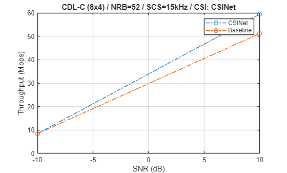
Display the measured throughput as a function of the SNR.
f=figure;
ax=gca;
plot(ax,simParameters.SNRIn, ...
1e-6*simResults.simThroughput/(simParameters.NFrames*10e-3), ...
'o-.','DisplayName',csiReportMode);
legend();
xlabel('SNR (dB)'); ylabel('Throughput (Mbps)'); grid on;
title(sprintf('%s (%dx%d) / NRB=%d / SCS=%dkHz / CSI: %s', ...
simParameters.DelayProfile, ...
simParameters.TransmitAntennaArray.NTxAnts, ...
simParameters.ReceiveAntennaArray.NRxAnts, ...
simParameters.Carrier.NSizeGrid, ...
simParameters.Carrier.SubcarrierSpacing, ...
char(csiReportMode)));
Compare Throughput with Conventional CSI Feedback
Enable generateBaseline to simulate and compare throughput using conventional CSI reporting methods based on TS 38.214 Section 5.2.2. This CSI report includes the following set of CSI indicators:
Rank indicator (RI)
Precoding matrix indicator (PMI)
Channel quality indicator (CQI)
For more information on the CSI report configuration, see the 5G NR Downlink CSI Reporting example.
generateBaseline =true; if generateBaseline && ~simParameters.CSIReportMode{"Type1SinglePanel"} f=figure; ax=gca; plot(ax,simParameters.SNRIn, ... 1e-6*simResults.simThroughput/(simParameters.NFrames*10e-3), ... 'o-.','DisplayName',csiReportMode); xlabel('SNR (dB)'); ylabel('Throughput (Mbps)'); grid on; title(sprintf('%s (%dx%d) / NRB=%d / SCS=%dkHz / CSI: %s', ... simParameters.DelayProfile, ... simParameters.TransmitAntennaArray.NTxAnts, ... simParameters.ReceiveAntennaArray.NRxAnts, ... simParameters.Carrier.NSizeGrid,simParameters.Carrier.SubcarrierSpacing, ... char(csiReportMode))); hold on; % Set simulation parameters for Type1SinglePanel method simParameters.CSIReportMode{csiReportMode} = false; simParameters.CSIReportMode{"Type1SinglePanel"} = true; simParameters.CSIReportConfig = hLoadCSIReportConfig(simParameters); % Set CSI feedback parameters for Type1SinglePanel method csiFeedbackOpts = getCSIFeedbackOptions(simParameters); csiParams.csiFeedbackOpts = csiFeedbackOpts; % Measure and plot throughput baselineSimResults = hThroughputSimulation(simParameters,csiParams, ... displaySimulationInformation = false); plot(ax,simParameters.SNRIn, ... 1e-6*baselineSimResults.simThroughput/(simParameters.NFrames*10e-3), ... 'o-.','DisplayName','Baseline'); legend() hold off; end
Simulating transmission scheme 1 (8x4) and SCS=15kHz with CDL-C channel at -10dB SNR for 2 10ms frame(s)
Using RI, PMI, and CQI as CSI feedback.

Throughput(Mbps) for 2 frame(s) = 8.4560

Simulating transmission scheme 1 (8x4) and SCS=15kHz with CDL-C channel at 10dB SNR for 2 10ms frame(s)
Using RI, PMI, and CQI as CSI feedback.

Throughput(Mbps) for 2 frame(s) = 51.2160
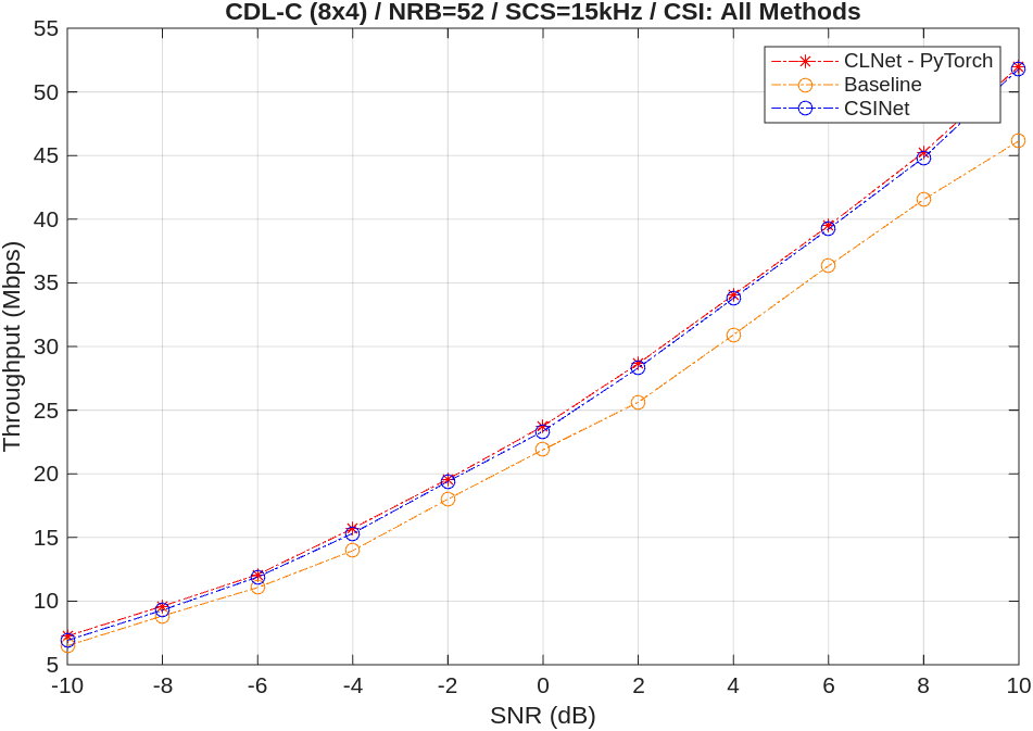
This figure shows throughput comparison of all the networks obtained by simulating 1000 slots (NFrames = 100, SNRIn = -10:2:10). The AI-based models provide similar throughput results that show higher throughput than the baseline conventional CSI reporting method.
Further Exploration
To customize and perform the throughput simulation, you can try:
Changing the parameters in
hConfigSimulationParameters.m (SeeNR PDSCH Throughput Using Channel State Information Feedback example for more details).Based on the changed parameters, train the networks using following examples:
CSINet - MATLAB: Train Autoencoders for CSI Feedback Compression example
CLNet - PyTorch: Offline Training and Testing of PyTorch Model for CSI Feedback Compression example
Local Functions
function csiFeedbackOpts = getCSIFeedbackOptions(simParameters)
% Create a CSI feedback algorithmic options structure

csiFeedbackOpts = struct();
csiFeedbackOpts.CSIReportMode = simParameters.CSIReportMode;
csiFeedbackOpts.CSIReportPeriod = simParameters.CSIReportConfig.Period;
csiFeedbackOpts.CSIReportConfig = simParameters.CSIReportConfig;
csiFeedbackOpts.PerfectChannelEstimator = simParameters.PerfectChannelEstimator;
csiFeedbackOpts.DMRSConfig = simParameters.PDSCH.DMRS;
if simParameters.CSIReportMode{"CSINet"}
    csiFeedbackOpts.AINetworkFilename = simParameters.AINetworkFilename;
    csiFeedbackOpts.Model = 'CSINet';

elseif simParameters.CSIReportMode{"CLNet - PyTorch"}
    if ~exist("savedModels","dir")
        unzip("CSISavedModels.zip",pwd);
    end
    csiFeedbackOpts.AINetworkFilename = simParameters.AINetworkFilename;
    csiFeedbackOpts.ExePath = simParameters.ExePath;
    csiFeedbackOpts.ExeMode = simParameters.ExeMode;
    csiFeedbackOpts.Model = 'CLNet';
else
    csiFeedbackOpts.Model = '';
end
end