Aerospace Coordinate System Examples for Unreal Engine Workflows
R2026bThis series of four short Aerospace Blockset™ examples demonstrates how to use four common aerospace coordinate systems in workflows involving Unreal Engine. The Unreal Engine® coordinate system is unlike any aerospace coordinate system; in addition, blocks in Aerospace Blockset provide different coordinate system transformation options than those in Simulink® 3D Animation. Coordinate system names used in Aerospace Blockset align with aerospace conventions whereas Simulink 3D Animation supports workflows in other domains; therefore, coordinate system naming conventions do not always align. This example is intended to demonstrate practical workflows, clarify the different conventions, and help users create models that contain both Aerospace Blockset and Simulink 3D Animation blocks.
Unreal Engine Coordinate System
The Unreal Engine coordinate system is a left-handed Cartesian coordinate system which uses units of centimeters and degrees.
Axes:
Positive X-axis points away from the viewer.
Positive Y-axis points to the right.
Positive Z-axis points upward.
Rotation:
Roll is clockwise rotation about the positive X-axis.
Pitch is clockwise rotation about the positive Y-axis.
Yaw is counterclockwise rotation about the positive Z-axis.
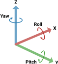
In the aerospace pack blocks, this coordinate system is labeled Target World, whereas in Simulink 3D Animation features it is labeled Default.
Aerospace Scenes
Each of the scenes in the aerospace library for Unreal Engine has a designated coordinate system. The vehicle pack blocks automatically synchronize their input coordinate system setting when one of these scenes is selected.
Scene | Coordinate System |
Apple Hill | NED |
Airport | NED |
Earth | ECI (ICRF) |
Geospatial (Cesium®), LLA origin | LLA |
Geospatial (Cesium), center origin | Fixed frame (ECEF, MCMF) |
Griffiss Airport | NED |
Moon | MCI (ICRF) |
Space | ICRF |
Underwater | NED |
The coordinate systems are NED (North-East-Down), ECI (Earth-Centered Inertial), ICRF (International Celestial Reference Frame), LLA (Latitude-Longitude-Altitude), ECEF (Earth-Centered, Earth-Fixed), MCMF (Moon-Centered, Moon-Fixed, or Mars-Centered, Mars-Fixed), and MCI (Moon-Centered Inertial). Related categories of coordinate systems are FF (fixed frame, like ECEF and MCMF) and IF (inertial frame, like ECI, MCI and ICRF).
NED: Airport Operations
The first example illustrates a variety of aircraft operations at the Airport. This scene uses the NED coordinate system. In Simulink 3D Animation, the equivalent coordinate system is labeled "AERO", and is an option in blocks such as Simulation 3D Camera Get.
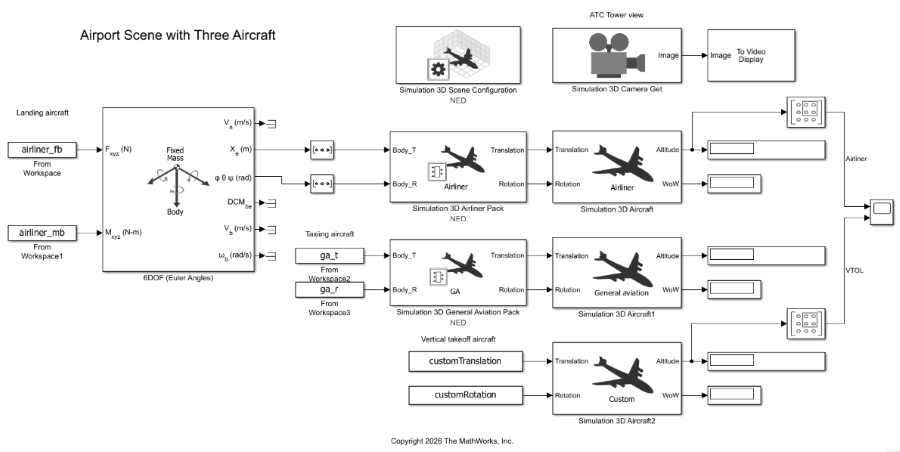
The landing airliner uses a 6DOF block for its dynamics, whereas the taxiing and VTOL aircraft use prescribed trajectories. The taxiing aircraft benefits from the NED-to-UE transformation in its pack block, whereas the VTOL aircraft needs to provide its translation and rotation data in the left-handed Unreal Engine coordinate frame. Run the initialization script, then open the model and press "Run" to simulate.
uecs1_init;
open_system('uecs1');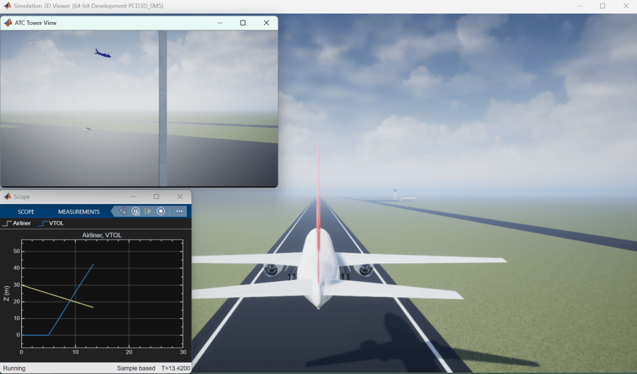
This composite view follows the airliner as it lands, with the air traffic control tower view in the top left showing the other two aircraft. A scope provides the altitudes of the Airliner and VTOL aircraft.
LLA: Aircraft Flight Operations
The second example illustrates an aircraft mission which uses both LLA and ECEF coordinate systems. The geospatial Cesium Earth scene is used with the Earth center as the origin, which sets the pack blocks to the ECEF coordinate system. However, aircraft mission information is in LLA. The LLA to ECEF Position and ECEF Position to LLA blocks provide conversions between the scene ECEF coordinate system and the LLA requirements of the mission.
In Simulink 3D Animation, the equivalent coordinate system for both FF and IF is labeled "MATLAB". All of these have the positive Z-axis pointing upward and use SI units.
An Attitude Profile (Nadir Pointing) block provides a reference vertical and flight path for orienting the aircraft, and the orientation of an antenna on the aircraft is referenced to it. In Aerospace Blockset, rotation angle vectors are organized in their rotation order. Unreal Engine assumes that rotation angles use the ZYX rotation order (yaw, pitch, roll), but requires the angles to be in the XYZ (roll, pitch, yaw) order. That is the reason for the Selector blocks reordering the angles after conversion from the quaternion provided by the Attitude Profile block.
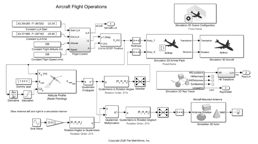
In the example model, the desired flight path is provided in LLA. A simulated antenna on the aircraft is dynamically pointed during the flight, with a ray trace showing its pointing direction and "hit" location on the ground. The hit location is output in LLA as well.
The flight path is the last section of the Custom Vertical Takeoff and Landing Example, which showcases Boston with Google Earth® tiles.
Open the model. Double-click the Simulation 3D Scene Configuration block to open its mask, navigate to the Geospatial tab and enter your Cesium Ion token. Then close the mask and press "Run" to simulate.
open_system('uecs2');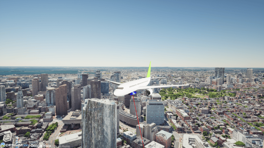
FF: Satellite Orbit and Rendezvous
The third example places two satellites in low-Earth orbit and aligns them with each other for rendezvous. The geospatial Cesium Earth scene is used again with the Earth center as the origin, which uses the ECEF coordinate system.
This example illustrates use of the Attitude Profile block for both geographic pointing and pointing at another dynamic object in the scene.
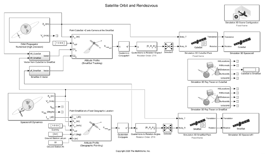
The CubeSat is placed in the slightly higher orbit and its Z-axis (camera face) is pointed towards the SmallSat. A ray trace gives the distance between them.
The SmallSat antenna face is pointed at a given geographic location on Earth, shown by a second ray trace.
Open the model. Double-click the Simulation 3D Scene Configuration block to open its mask, navigate to the Geospatial tab and enter your Cesium Ion token. Then close the mask and press "Run" to simulate.
open_system('uecs3');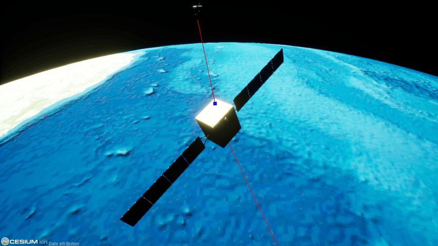
Under the given conditions, the ground station is on the opposite side of the Earth from the satellites, so the visible ray intersection with the Earth is not at the ground station.
IF: Lunar Free-Return Mission
The fourth example illustrates a lunar free-return mission, where a vehicle leaves Earth orbit on a trajectory that takes it around the Moon and back to Earth atmospheric reentry without additional engine burns. The Earth scene is used, which includes the Moon. Missions like this use the ICRF coordinate system.
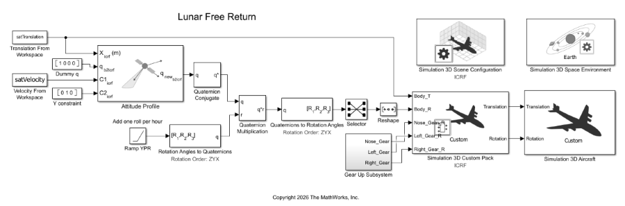
This model uses position and velocity data from the Model a Lunar Free-Return Trajectory in Satellite Scenario Using Numerical Orbit Propagation example. Open the model and run the initialization script, then press "Run" to simulate. The full simulation is 597,900 seconds (6.9 days) long, and therefore can take a number of minutes to complete with its 60-second time step. Note that the maximum time step that any aerospace Unreal Engine scene can accept is 60 seconds.
open_system('uecs4');
uecs4_init;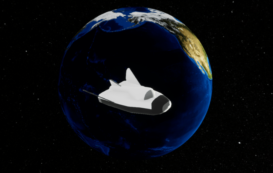
This image captures the spacecraft as it is just leaving Earth orbit and heading towards the Moon.

