Simscape Thermal Test Harness for Electric Vehicles
R2026bThe Simscape thermal test harness represents a complete electric vehicle thermal management system (EVTMS) that includes a heat pump for cabin heating. The plant model is a Simscape model that includes two coolant loops, a refrigerant loop, and a cabin air heating, ventilation, and air conditioning (HVAC) loop. Use this test harness to design thermal control algorithms, analyze energy consumption, or evaluate heat pump performance.
Note
The Simscape plant model is similar to the model used in the Electric Vehicle Thermal Management with Heat Pump (Simscape Fluids) example.
To create and open a working copy of the thermal test harness project, use one of these commands.
The 'constant' variant uses steady-state heat loads, and the
'dynamic' variant uses time-varying heat loads from a drive cycle.
The variants share the same thermal plant and controller. Only the Heat
Flow subsystem differs.
The model contains subsystems representing these thermal elements:
Refrigerant loop with compressor, condenser evaporator, inner condenser, evaporator, chiller, heat exchanger, and three expansion valves
Battery and DC-DC coolant loop with electric heater and chiller
Motor coolant loop with radiator
Cabin HVAC with blower, positive temperature coefficient (PTC) heater, and blend door
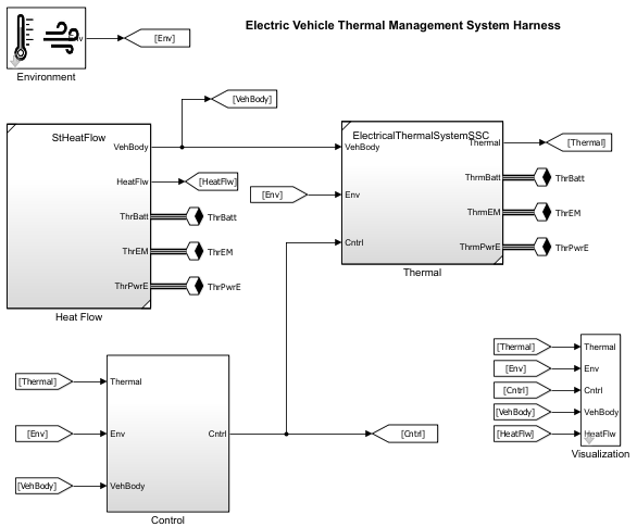
This table describes the subsystems in the test harness.
| Test Harness Subsystem | Description |
|---|---|
| Implements ambient conditions including temperature, barometric pressure, relative humidity, and CO2 fraction. |
| Implements the Simscape model containing the refrigerant loop, battery coolant loop, motor coolant loop, and cabin HVAC loop. This subsystem is the core thermal plant model. |
| References the |
| Provides external heat loads to the thermal plant through Simscape thermal ports. Simulates battery, motor, and DC-DC converter internal losses. |
| Displays thermal system performance including component power
consumption, temperatures, and total HVAC power through the
|
Thermal Plant
The Thermal subsystem contains the complete Simscape model of two
liquid coolant loops, a refrigerant loop, and a cabin air HVAC loop.
This table describes the fluid loops and their key components.
| Loop | Component | Description |
|---|---|---|
Refrigerant |
| Drives the flow in the refrigerant loop. Maintains a cabin air vent temperature setpoint. Turns off when transitioning between cold loop mode and heat pump mode. |
| Rectangular tube-and-fin heat exchanger that transfers heat from the refrigerant to ambient air in cold loop mode or transfers heat from ambient air to the refrigerant in heat pump mode. Vehicle speed and the radiator fan drive the airflow. | |
| Rectangular tube-and-fin heat exchanger that transfers heat from the refrigerant to cabin air in heat pump mode. In cold loop mode, the blend door directs cabin air to bypass the inner condenser. | |
| Rectangular tube-and-fin heat exchanger that transfers heat from cabin air to the refrigerant. Also dehumidifies the cabin air. | |
| Shell-and-tube heat exchanger that transfers heat from the coolant to the refrigerant to cool the battery coolant loop. | |
| Tube bank heat exchanger that transfers heat from the coolant to the refrigerant. Improves heat pump mode efficiency by allowing the refrigerant loop to reuse waste heat from the batteries and power electronics. | |
| In cold loop mode, directs refrigerant through the chiller and evaporator to cool the batteries and cabin. In heat pump mode, directs refrigerant to the heat exchanger, bypassing the chiller and evaporator. | |
| Provides the pressure drop needed to vaporize the refrigerant entering the evaporator in cold loop mode. | |
| Provides the pressure drop needed to vaporize the refrigerant entering the chiller in cold loop mode. | |
| Provides the pressure drop needed to vaporize the refrigerant entering the condenser evaporator in heat pump mode. Fully open in cold loop mode to allow refrigerant to pass through with minimal losses. | |
Battery/DCDC Coolant |
| Drives the coolant loop that thermally conditions the batteries and DC-DC converter. |
| Thermal mass surrounded by a coolant jacket. | |
| Coolant jacket around the DC-DC converter, represented by a heat flow rate source and a thermal mass. | |
| Battery heater that turns on in cold weather to warm the battery. Contains a heat flow rate source and a thermal mass. | |
Motor Coolant |
| Drives the coolant loop that cools the motor. |
| Coolant jacket around the motor, represented by a heat flow rate source and a thermal mass. | |
| Rectangular tube-and-fin heat exchanger that dissipates coolant heat to ambient air. The airflow passes through the condenser evaporator before the radiator. Vehicle speed and the fan drive the airflow. | |
| In cold loop mode, directs coolant to the radiator to reject heat. In heat pump mode, directs coolant to the heat exchanger to transfer waste heat to the refrigerant. | |
| Three-way valve that switches the coolant loops between parallel mode (battery and motor loops operate independently) and serial mode (loops connected in series for heat pump operation). | |
| Three-way valve that works with | |
Cabin Air |
| Moist air flow rate source that drives cabin air through the HVAC ducts. Includes a recirculation flap that controls the mix of fresh outside air and recirculated cabin air. |
| Constant-volume moist air chamber representing the cabin interior. Includes heat transfer to the environment, air leakage, and occupant heat, moisture, and CO2 gains. | |
| Positive temperature coefficient air heater that warms cabin air downstream of the evaporator. Includes temperature auto-regulation to limit element temperature. | |
| Directs cabin air through or around the inner condenser. In heat pump mode, routes air through the inner condenser to heat the cabin. In cold loop mode, bypasses the inner condenser. |
Power Consumption Measurement
The model measures power consumption for seven actuators. To plot power consumption at
the component and system level, double-click the Visualization block
and click Plot power [W].
The model measures power for these components.
| Component | Measurement Method |
|---|---|
| Torque sensor multiplied by angular velocity. |
| Torque sensor multiplied by angular velocity. |
| Torque sensor multiplied by angular velocity. |
| Torque sensor multiplied by angular velocity. |
| Controlled heat flow rate source output. |
| Controlled heat flow rate source output. |
| Simscape blower power measurement. |
Controllers
The Control subsystem references the
ThermalControl.slx model, which implements a powertrain and cabin
thermal control strategy. This table describes controller outputs according to the
physical system they control. In the model, a single Stateflow® chart implements all control functions. The chart uses subcharts for
compressor speed, pump speeds, valve positions, and cabin climate commands.
| Controller Function | Description |
|---|---|
Compressor control | Regulates compressor speed to maintain a cabin air vent temperature setpoint. Turns off when transitioning between cold loop mode and heat pump mode. |
Pump control | Commands battery and motor pump speeds based on coolant temperature targets. |
Valve control | Manages series/parallel mode valves, radiator bypass, and refrigerant bypass to route coolant flow. |
Cabin climate control | Controls blower speed, PTC heater, blend door, and recirculation flap to maintain cabin temperature and humidity targets. |
The controller uses setpoints and parameters defined in the
Controller block. To change a setpoint, double-click the
Controller block in
ThermalControl.slx.
| Parameter | Description |
|---|---|
| Cabin air temperature target. |
| Battery coolant temperature target. |
| Electric motor coolant temperature target. |
| DC-DC converter coolant temperature target. |
| Cabin relative humidity target. |
| Minimum ambient temperature for heat pump mode activation. |
| Controller startup delay before thermal management activates. |
In manual mode, the Controller block mask also provides direct
controls for cabin blower speed, blend door position, and recirculation flap
setting.
Heat Flow Sources
The Heat Flow subsystem provides external heat loads to the thermal
plant through three Simscape thermal ports. The heat flow model is a referenced
subsystem that differs between the constant and dynamic variants.
| Thermal Port | Description |
|---|---|
ThrBatt | Battery thermal port. Injects heat flow representing battery internal losses during charging and discharging. |
ThrEM | Electric motor thermal port. Injects heat flow representing motor electromagnetic and mechanical losses. |
ThrPwrE | Power electronics thermal port. Injects heat flow representing DC-DC converter losses. |
Constant Heat Flow
The Constant variant uses fixed heat load values for
steady-state thermal analysis.
| Source | Description |
|---|---|
| Constant battery internal losses. |
| Constant motor losses per electric motor. |
| Constant DC-DC converter losses. |
| Constant vehicle speed for ram air cooling calculation. |
Dynamic Heat Flow
The dynamic variant reads time-varying heat loads from
InputSignals.mat, representing a realistic drive
cycle.
| Signal | Description |
|---|---|
| Drive-cycle battery losses. Negative values indicate heat absorption during regenerative braking. |
| Drive-cycle motor losses per electric motor. |
| Drive-cycle DC-DC converter losses. |
| Drive-cycle vehicle speed for ram air cooling calculation. |
See Also
Scenarios | Powertrain and Cabin Thermal Control

