Configure AUTOSAR Ports By Using Simulink Bus Ports
In classic and adaptive AUTOSAR software components, you can model AUTOSAR ports by using root-level Simulink® bus ports instead of Inport and Outport blocks. Bus port blocks In Bus Element and Out Bus Element can simplify model interfaces. For more information, see Simplify Subsystem and Model Interfaces with Bus Element Ports.
Bus port blocks provide a more intuitive way to model AUTOSAR communication ports, interfaces, and groups of data elements. If you model AUTOSAR ports with In Bus Element and Out Bus Element blocks, and type the bus ports by using bus objects, basic properties of AUTOSAR ports, interfaces, and data elements are configured without using the AUTOSAR Dictionary. To manage component interfaces, you configure Simulink bus objects.
You can use root-level bus ports with:
AUTOSAR software components that use rate-based or export-function modeling styles.
AUTOSAR signal-based communication.
AUTOSAR message-based communication, including classic queued sender-receiver (S-R) or adaptive event-based messaging.
In AUTOSAR architecture models, you can link Classic Platform component models that have bus ports and then use the Schedule Editor to schedule the simulation.
Model AUTOSAR Ports By Configuring Simulink Bus Ports
To configure Simulink bus ports in an AUTOSAR model:
Create or open an AUTOSAR software component model. The examples in this topic use a writable copy of the example model
autosar_swc.Add two In Bus Element blocks to the model and connect them as root input ports. Configure the bus ports to share the same AUTOSAR port but have different elements. The bus port blocks are automatically mapped to AUTOSAR ports and elements.
Delete the existing Inport blocks in the model.
Create an In Bus Element block. Open the block parameters dialog box. Set Port name to
ReceivePortand the signal name toIn1.Connect the block to the first input signal. Make a copy of the block and connect it to the second input signal. In the model canvas (not the block parameters dialog box), click the name of the second block and change
In1toIn2.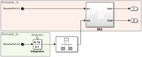
The In Bus Element block parameters dialog box now lists both signals.
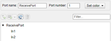
Edit each signal and set the Sample time to 1 and 2, respectively.
Add two Out Bus Element blocks to the model and connect them as root output ports. Configure the bus ports to share the same AUTOSAR port but have different elements. The bus port blocks are automatically mapped to AUTOSAR ports and elements.
Delete the existing Outport blocks in the model.
Create an Out Bus Element block. Open the block parameters dialog box. Set Port name to
SenderPortand the signal name toOut1.Connect the block to the first output signal. Make a copy of the block and connect it to the second input signal. In this case, the signal name is automatically set to
Out2.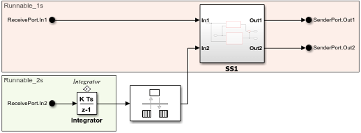
The Out Bus Element block parameters dialog box now lists both signals.
From the Apps tab, open the AUTOSAR Component Designer app.
Use the Code Mappings editor to verify that the rate-based functions are mapped to AUTOSAR runnables.
On the Inports tab change the DataAccessMode for both input bus ports to
ImplicitReceive.Verify that the input bus element are mapped to port
ReceiverPort.On the Outports tab change the DataAccessMode for both output bus ports to
ImplicitSend.Verify that the output bus elements are mapped to port
SenderPort.
If you generate code for the model:
The generated ARXML file
autosar_swc_component.arxmldescribes periodic runnables for each sample rate, namedRunnable_1sandRunnable_2s.The generated code file
autosar_swc.cdefines the rate-based functionsRunnable_1sandRunnable_2s.
Model AUTOSAR Interfaces By Typing Bus Ports with Bus Objects
To define an AUTOSAR interface, type a bus port with a bus object. This example
uses the same AUTOSAR software component model that was modified in the previous
example. The example replaces the sender interface Output_If in
autosar_swc with a new interface named
SenderInterface which is defined by a bus object.
With the modified
autosar_swcopen, open the Type Editor. On the Modeling tab, in the Design gallery, select Type Editor.In the Type Editor, add a
Simulink.Busobject and name itSenderInterface. Add twoSimulink.BusElementobjects and name themOut1andOut2.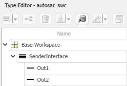
Open the
SenderPortblock dialog box. Pause on the bus object namedSenderPortand click the pencil icon that appears. Set the Data type of the bus object toBus: SenderInterface.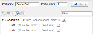
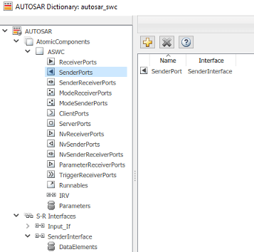
Because the new interface is replacing an existing mapped interface, you must explicitly delete the existing sender port and sender interface. Open the AUTOSAR Component Designer app and open AUTOSAR Dictionary. Select and delete sender port
SenderPortand S-R interfaceOutput_If.To generate and map the new sender interface, either call function
autosar.api.createto update the model mapping or press Ctrl+B to generate model code (requires Embedded Coder®). Here is theautosar.api.createfunction call.autosar.api.create('autosar_swc');Optionally, open the AUTOSAR Dictionary and view the new sender port and S-R interface definitions.
See Also
In Bus Element | Out Bus Element | autosar.api.create
Related Examples
More About
You can also select a web site from the following list
Americas
- América Latina (Español)
- Canada (English)
- United States (English)
Europe
- Belgium (English)
- Denmark (English)
- Deutschland (Deutsch)
- España (Español)
- Finland (English)
- France (Français)
- Ireland (English)
- Italia (Italiano)
- Luxembourg (English)
- Netherlands (English)
- Norway (English)
- Österreich (Deutsch)
- Portugal (English)
- Sweden (English)
- Switzerland
- United Kingdom (English)
Asia Pacific
- Australia (English)
- India (English)
- New Zealand (English)
- 中国
- 日本Japanese (日本語)
- 한국Korean (한국어)