Out Bus
								Element
Specify output of external port
Libraries:
Simulink /
Ports & Subsystems
Simulink /
Sinks
HDL Coder /
Ports & Subsystems
HDL Coder /
Sinks
Alternative Configurations of Out Bus Element Block:
Bus Element Out
Description
The Out Bus Element block provides a bus, signal, or message as the output of an external port.
To group multiple buses, signals, or messages into an output bus, use multiple Out Bus Element blocks that correspond with the same port. The Out Bus Element blocks combine the functionality of a Bus Creator block and an Outport block. All Out Bus Element blocks that correspond with the same port share a dialog box.
For interfaces that include buses composed of many bus elements, Out Bus Element blocks:
Reduce signal line complexity and clutter in a block diagram.
Allow you to more easily make incremental changes to the interface.
Allow access to a bus element closer to the point of usage, avoiding the use of a Bus Creator and From block configuration.
To convert an interface to use Out Bus Element blocks, see Simplify Subsystem and Model Interfaces with Bus Element Ports.
The Out Bus Element block does not support mixing message and signal elements as inputs.
When you save output data to the workspace or a file, bus data defined by groups of root-level Out Bus Element blocks are logged along with root-level Outport block data.
Examples
In a component such as a subsystem or model, each output bus element port is represented by one or more Out Bus Element blocks. How you create a bus element port depends on whether you are in the component or its parent.
In a component — To add an output bus element port to the current subsystem or model, add an Out Bus Element block.
In a component — To create another output bus element port from inside a component, Ctrl+drag an existing Out Bus Element block to a new location and click New Port.

Alternatively, copy and paste the block, or add another Out Bus Element block from the quick-insert menu.
In a parent — To add an output bus element port to a subsystem or model, click the edge of the corresponding Subsystem or Model block. Then, click Create out bus port.
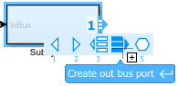
When you create an output bus element port, an Out Bus
Element block with a unique port name appears in the
corresponding subsystem or model. The default port name is
OutBus.
In a component such as a subsystem or model, each output bus element port is represented by one or more Out Bus Element blocks. How you rename a bus element port varies.
In a component — Click the port name in the Out Bus Element block label. Then, enter a new name.

In a parent — Click the port name in the Subsystem or Model block icon. Then, enter a new name.

In the Property Inspector — Select the port or a block associated with the port. Then, set the Port name parameter.
When multiple blocks are associated with the same port and you change the name of the port, the behavior depends on whether the new port name matches an existing port name.
If a port with the specified name exists, changing the port name assigns the block to the specified port. (since R2026a)
If a port with the specified name does not exist, changing the port name renames the port. The corresponding blocks update to reflect the new port name.
When you have only one Out Bus Element block for a port, you can pass the block input to the output port without nesting it in a bus.
Open and compile the example model named SignalOutputBusPort. To compile the model, on the Modeling tab of the Simulink® Toolstrip, click Update Model or Run. Compiling the model updates the line styles, which you can use to visually identify buses.
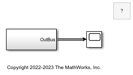
A Subsystem block has an output port that passes a bus to a Scope block.
To view the Out Bus Element block that corresponds with the output port, open the subsystem.
![]()
In the subsystem, a Sine Wave block connects to an Out Bus Element block. Based on the block label, OutBus.signal1, the port output is a bus that contains an element named signal1. The dot in the block label indicates the bus hierarchy.
To pass the signal to the output port without nesting it in a bus, delete the second text field from the block label. For example, click signal1 to edit the text field.
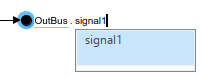
Then, delete signal1. To commit the change, click elsewhere on the canvas.
![]()
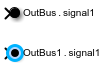
To change the name of the port associated with the block, edit the first text field in the block label. For example, click OutBus to edit the text field.
![]()
Then, delete OutBus and enter SineWave. Ignore the placeholder text that shows where you can enter an element name.
![]()
Alternatively, set the Port name block parameter to the desired name for the port.
Navigate up to the parent model and recompile.
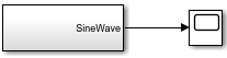
The output port of the Subsystem block now passes a signal rather than a bus to the Scope block.
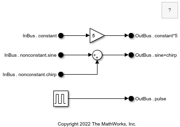
To provide multiple signals to one output port, use an Out Bus Element block for each signal that you want in the output.
Open the model named BusOutputPort.
An Out Bus Element block writes to an element named signal1 of a port named OutBus.
To rename an element, edit the second text field in the block label. For example, double-click signal1 and enter constant``*5.
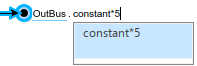
Open the Property Inspector. Then, select the Out Bus Element block. Alternatively, double-click the block to open a dialog box.
![]()
The signal that the block selects is highlighted.
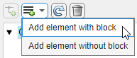
To add an element to the port with a block:
Select the element that you want to contain the new element. For this example, select
OutBus.Click
 and select Add element with block.
An Out Bus Element block labeled OutBus.signal2 appears in the block diagram.
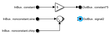
In the Property Inspector or dialog box, double-click the name signal2 and enter sine+chirp.
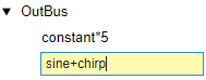
The corresponding block label updates.
Connect the new Out Bus Element block to the unconnected port of the Sum block.
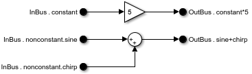
All element names associated with the same output port must be unique. The software does not support overlapping writes to an output element.
The default Out Bus Element block nests the output element in a bus. When the output port has many elements, organize the elements in nested buses within the output bus.
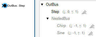
Open the model named OutputBusPortHierarchy, which contains three Out Bus Element blocks.
Each dot in an Out Bus Element block label indicates a new level of hierarchy. To nest an element under another bus in the output bus, edit the second text field of the corresponding block label and add a dot after each nested bus in the hierarchy.
For example, click the label constant``*5. Then, change it to NestedBus.constant``*5.
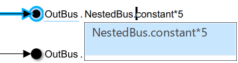
This label creates an intermediate bus named NestedBus that contains constant``*5.
To add elements to the new bus, you can similarly edit other block labels. Alternatively, double-click an Out Bus Element block or open the Property Inspector and select an Out Bus Element block.
To move elements within the output bus, select the elements to move and drag them to a new location. For example, drag the signal named sine+chirp into the nested bus.
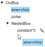
The block label indicates the new hierarchy.
![]()
In the Property Inspector or dialog box, you can add elements under an existing element in the bus hierarchy. Select the element that you want to contain a new element. Then, click ![]() and select Add element with block or Add element without block.
and select Add element with block or Add element without block.
When an Out Bus Element block represents the element that you want to contain a new element, to avoid conflicts, your only option is Add element without block.
Since R2024a
To specify the elements of a bus at a bus element port, you can:
Add elements to the interface with or without adding blocks to the block diagram.
Define the bus hierarchy with a
Simulink.Busobject.
This example shows how to define a bus at an output bus element port without a
Simulink.Bus object.
In a blank model or subsystem, add an Out Bus Element block.
![]()
Open the Property Inspector. Then, select the Out Bus Element block. Alternatively, double-click the block to open a dialog box.
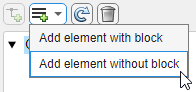
To add an element to the port without a block, select the element that you
want to contain the new element. For example, select
OutBus. Then, click ![]() , and select Add
element without block.
, and select Add
element without block.
The new element is nested under the previously selected element. The block diagram is unchanged.

The element name is gray and italicized to indicate that an Out Bus Element block does not represent the element directly.
By adding elements without adding blocks, you can define the entire output
bus hierarchy with only one Out Bus Element block and without
a Simulink.Bus object.
Optionally:
Add more elements with or without blocks.
Rename elements by double-clicking their names and entering new names.
Reorder elements by dragging them to new locations.
Specify element properties.
Defining the elements at an output port is useful when you create a file for reuse. The interface definition validates the hierarchy and properties of the output bus that the component provides.
Tip
When you want to add many elements without blocks, using the
Simulink.Bus.addElementToPort function can be
quicker than using the dialog box. For an example, see Programmatically Create Bus Element Ports.
Suppose you add elements without blocks then decide that you want
Out Bus Element blocks to represent the elements. To add
a block for an output element, click an element name. Then, click ![]() . For example, add a block for the element
named
. For example, add a block for the element
named
Chirp.
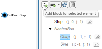
In the block diagram, an Out Bus Element block labeled
OutBus.NestedBus.Chirp appears.
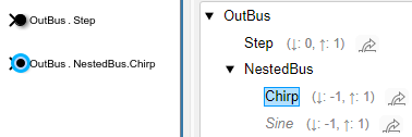
You cannot add blocks for elements that an existing Out Bus
Element block represents. For example, you cannot add a block
for NestedBus. The Out Bus Element block
labeled OutBus.NestedBus.Chirp already represents
NestedBus because NestedBus is the
parent bus for Chirp.
Use compact labels and block colors to customize the appearance of In Bus Element and Out Bus Element blocks.
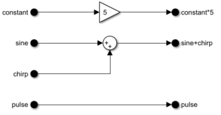
Open the model named BusElementPortBlocks.
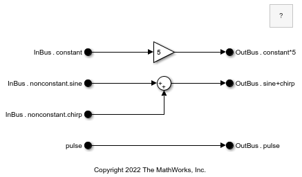
The model contains:
In Bus Element blocks that represent two unique bus element ports named
InBusandpulseOut Bus Element blocks that represent a bus element port named
OutBus
To reduce the size of the block labels, display only the leaf element names. Select an In Bus Element or Out Bus Element block, pause on the ellipsis, and in the action bar, click Compact Notation.
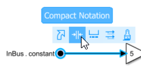
All In Bus Element and Out Bus Element blocks in the block diagram display shortened block labels that use only the leaf element name.
To show the full block label, in the action bar, you can click Expanded Notation. For this example, keep the compact block labels.
Block colors can help differentiate unique ports when the block labels are compact.
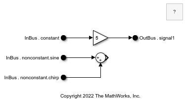
Open the Property Inspector. Then, select an In Bus Element block that corresponds with the port named InBus. For example, select the block labeled constant. Alternatively, double-click the block to open a dialog box.
In the Property Inspector or dialog box, select InBus. Then, click ![]() and select a standard color or specify a custom color. For this example, select cyan.
and select a standard color or specify a custom color. For this example, select cyan.
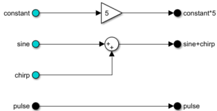
The blocks related to the port use the chosen color.
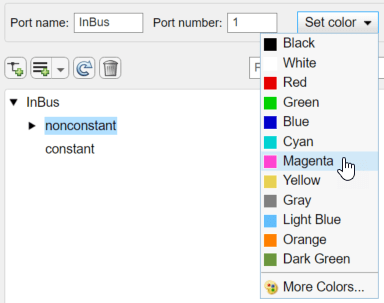
To identify the blocks that select the nested bus named nonconstant or its elements, select nonconstant. Then, click ![]() and select a standard color or specify a custom color. For this example, select magenta.
and select a standard color or specify a custom color. For this example, select magenta.

The blocks related to the nested bus use the chosen color.

Extended Examples
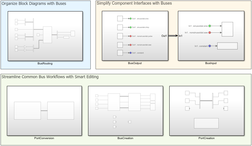
Simulink Bus Capabilities
Work with buses in components, simplify component interfaces, and streamline common bus workflows.
Programmatically Create Bus Element Ports
Add blocks for bus element ports and specify element attributes using MATLAB® functions.

Use Model-Based Design to Build a Battery Management System
Build a battery management system using a workflow that highlights the best practices and tools for collaborative design.
Ports
Input
Parameters
To edit the element associated with an Out Bus Element block, in the Simulink® Editor, edit the block label.
To edit port, signal, and execution attributes, use the Property Inspector. From the Simulink Toolstrip, on the Simulation tab, in the Prepare gallery, select Property Inspector.
Block Label
Specify a port name that is not already in use by another block or port within the system. The name appears on the parent Subsystem or Model block.
To change the port name from the Simulink Editor, edit the first text field of the block label.
![]()
Multiple blocks can provide output for the same port as long as each block provides output for a unique element of the port.
Programmatic Use
To set the block parameter value programmatically, use
the set_param function.
| Parameter: | PortName |
| Values: | "OutBus" (default) | port name in quotes |
| Data Types: | char | string |
Example: set_param("mymodel/Subsystem1/PortBlock",PortName="myBus")
To create a bus at the output port, specify an element in the second text field of the block label.

How you specify the element depends on where the element is in the bus hierarchy.
For an element at the top level of the output bus, specify the element name, for example,
constant.For an element in a nested bus, specify the name of the nested bus, intermediary nested buses, and the leaf signal separated by dots, for example,
sinusoidal.sine. This element path does not include the top-level bus.
Each output element must be unique and must not overlap with other elements of the port. For example, for a nested bus, use one Out Bus Element block that corresponds with the nested bus or multiple Out Bus Element blocks that correspond with the nested bus elements.
To output a signal, message, or bus without creating a bus, delete the text from the second text field of the block label.
Programmatic Use
To set the block parameter value programmatically, use
the set_param function.
| Parameter: | Element |
| Values: | "signal1" (default) | element path in quotes |
Example: set_param("mymodel/Subsystem1/PortBlock",Element="constant")
Example: set_param("mymodel/Subsystem1/PortBlock",Element="sinusoidal.sine")
Port Tab
To toggle whether the tabs are visible, click ![]() .
.
Before R2025a: To specify attributes, such as output name,
pause on the name of the top-level bus, signal, or message. Then, click ![]() . Alternatively, when available, click an
attribute summary.
. Alternatively, when available, click an
attribute summary.
For information about the port name, see Port name.
Specify the order in which the port that corresponds to the block appears on the parent Subsystem or Model block.
If you add a block that creates another port, the port number is the next available number.
Deleting all blocks associated with a port deletes the port. Other ports are renumbered so that they are sequential and do not skip any numbers.
Specifying a port number that exceeds the number of ports creates a port for that number and for any skipped sequential numbers.
Programmatic Use
To set the block parameter value programmatically, use
the set_param function.
| Parameter: | Port |
| Values: | "1" (default) | real integer in quotes |
| Data Types: | char | string |
Example: set_param("mymodel/Subsystem1/PortBlock",Port="5")
Since R2023a
Specify the name of the output bus, signal, or message in the parent subsystem or model. The name appears as a label on the line.
To display propagated labels for individual lines or all lines in a model, see Display Propagated Signal Labels.
Dependencies
To enable this parameter:
The block must be at the top level of a model.
The element must be the top-level bus, signal, or message.
When you set Data type to a
Simulink.Busobject, the software sets this parameter to""(empty).
Programmatic Use
To programmatically set the attribute value for an element, use the set_param function. Specify the element as the model name or subsystem block
path, a forward slash, and the port name or bus element path. For a bus element port, the
bus element path provides the hierarchy from the top-level bus to the target element,
separating each name in the hierarchy with a dot.
| Parameter: | OutputName |
| Values: | "" (default) | output name in quotes |
| Data Types: | char | string |
Example: set_param("mymodel/OutBus",OutputName="model-output")
Since R2024b
For conditionally executed subsystems, specify the block output before the subsystem executes and while the subsystem is disabled. To inherit the initial output value from the input signal, apply both of these default settings:
Set Initial output to
[].Set Output when disabled to
held.
The software attempts to inherit the output value from the input
signal. If the input signal is not a valid source for the initial output
value, the initial output value [] is treated as
double(0). For more information, see Conditional Subsystem Initial Output Values.
For information about specifying an initial condition structure, see Specify Initial Conditions for Bus Elements.
Tips
If the conditional subsystem is driving a Merge block, you do not need to specify an initial condition for the Out Bus Element block. For more information, see Underspecified initialization detection.
Dependencies
To enable this parameter:
The block must be at the top level of a conditionally executed subsystem or model.
The element must be the top-level bus, signal, or message.
Limitations
This block does not support an initial output of
inforNaN.When the input is a virtual bus, an Initial output value of
[]is treated asdouble(0).When the input contains a nonvirtual bus, Initial output does not support nonzero scalar values.
Programmatic Use
To set the block parameter value programmatically, use
the set_param function.
| Parameter: | InitialOutput |
| Values: | '[]' (default) | scalar in quotes | structure in quotes |
| Data Types: | char | string |
Example: set_param("mdl/condss/Output",InitialOutput="3")
Since R2024b
Specify what happens to the block output when the parent conditionally executed subsystem is disabled.
held— The output is held when the subsystem is disabled.reset— The output is reset to the value given by Initial output when the subsystem is disabled.
Tips
If the output of the parent subsystem connects to a Merge block, do not set this parameter to
reset.For an Out Bus Element block in a function-call subsystem, this parameter is meaningful only if the Function-Call Subsystem block connects to a state in a Stateflow® chart. For more information, see Control Function-Call Subsystems (Stateflow).
Dependencies
To enable this parameter:
The block must be at the top level of a conditional subsystem with valid enabling and disabling semantics. For example, an Out Bus Element block in an enabled subsystem supports this parameter, but an Out Bus Element block in a triggered subsystem does not support this parameter.
The element must be the top-level bus, signal, or message.
Programmatic Use
To set the block parameter value programmatically, use
the set_param function.
| Parameter: | OutputWhenDisabled |
| Values: | "held" (default) | "reset" |
Example: set_param("mdl/condss/Output",InitialOutput="3",OutputWhenDisabled="reset")
Signal Tab
To toggle whether the tabs are visible, click ![]() .
.
When you specify attributes, a parenthetical appears next to the name of the corresponding bus, signal, or message. To display the specified attributes in full, click the attribute summary.
![]()
Before R2025a: To specify attributes, such as data type, pause on the
name of a bus, signal, or message. Then, click ![]() . Alternatively, when available, click an attribute
summary.
. Alternatively, when available, click an attribute
summary.
The data type of a bus, signal, or message can be inherited, specified directly, or expressed as a data type object.
| Data Type | Description |
|---|---|
| Inherited data type | Specify |
Built-in Simulink data type | Specify a data type. For example, specify
|
| Fixed-point data type | Use the |
| Enumerated data type | Use the name of the type preceded by
|
| Bus data type | Use the name of the Some parameters of
the element are reset to their default values. For
example, the Min,
Max, and
Unit parameters are reset.
The software uses the corresponding properties of
the When you specify a bus using a
To create and assign
Dependencies An In Bus Element block must represent the bus or an element of the bus. |
| Value type | Use the name of the Some parameters of
the element are ignored. Instead, the software uses
the corresponding properties of the
|
| Custom data type | Use a MATLAB expression that specifies the type.
For example, you can specify a |
To create and edit data type objects using the Type Editor, click ![]() .
.
Programmatic Use
To programmatically set the attribute value for an element, use the set_param function. Specify the element as the model name or subsystem block
path, a forward slash, and the port name or bus element path. For a bus element port, the
bus element path provides the hierarchy from the top-level bus to the target element,
separating each name in the hierarchy with a dot.
| Parameter: | OutDataTypeStr |
| Values: | "Inherit: auto" (default) | "double" | "single" | "half" | "int8" | "uint8" | "int16" | "uint16" | "int32" | "uint32" | "int64" | "uint64" | "boolean" | "fixdt(1,16)" | "fixdt(1,16,0)" | "fixdt(1,16,2^0,0)" | "string" | "Enum: <class name>" | "Bus: <object name>" | "ValueType: <object
name>" | data type expression in quotes |
Example: set_param("mymodel/myBus.signal1",OutDataTypeStr="int32")
Specify the data mode of the output element.
inherit— Output element inherits its data mode.signal— Output element must be a signal or a bus that contains signals.message— Output element must be a message or a bus that contains messages.
Dependencies
To enable this parameter, the block must be at the top level of a model.
Programmatic Use
To programmatically set the attribute value for an element, use the set_param function. Specify the element as the model name or subsystem block
path, a forward slash, and the port name or bus element path. For a bus element port, the
bus element path provides the hierarchy from the top-level bus to the target element,
separating each name in the hierarchy with a dot.
| Parameter: | DataMode |
| Values: | "inherit" (default) | "signal" | "message" |
Example: set_param("mymodel/OutBus",DataMode="signal")
Specify whether to inherit the bus virtuality or define the bus as virtual or nonvirtual. For more information, see Composite Interface Guidelines.
This parameter determines whether the blocks inherit or define the bus virtuality. If the blocks define the bus virtuality and the virtuality of the input bus does not match, compiling the model produces an error.
Dependencies
To enable this parameter, Data type must resolve to a
Simulink.Bus object. For example, set Data type to
a Simulink.Bus object or a Simulink.ValueType object that
specifies a Simulink.Bus object as its data type.
Programmatic Use
To programmatically set the attribute value for an element, use the set_param function. Specify the element as the model name or subsystem block
path, a forward slash, and the port name or bus element path. For a bus element port, the
bus element path provides the hierarchy from the top-level bus to the target element,
separating each name in the hierarchy with a dot.
| Parameter: | BusVirtuality |
| Values: | "inherit" (default) | "virtual" | "nonvirtual" |
Example: set_param("mymodel/myBus.nestedBus",BusVirtuality="nonvirtual")
Specify the dimensions of a signal.
-1— The signal can have any dimensions.N— The signal must be a vector of sizeN.[R C]— The signal must be a matrix havingRrows andCcolumns.
Dependencies
When Data type specifies a
Simulink.Busobject, the software sets this parameter to1. The software uses the dimensions specified by theSimulink.BusElementobjects in theSimulink.Busobject.When Data type specifies a
Simulink.ValueTypeobject, the software ignores the value of this parameter. The software uses the dimensions specified by theSimulink.ValueTypeobject instead.
Programmatic Use
To programmatically set the attribute value for an element, use the set_param function. Specify the element as the model name or subsystem block
path, a forward slash, and the port name or bus element path. For a bus element port, the
bus element path provides the hierarchy from the top-level bus to the target element,
separating each name in the hierarchy with a dot.
| Parameter: | PortDimensions |
| Values: | "-1" (default) | integer in quotes | 1-by-2 vector of integers in
quotes |
| Data Types: | char | string |
Example: set_param("mymodel/myBus.signal1",PortDimensions="[1
3]")
Specify the type of signals allowed.
Inherit— Allow variable-size and fixed-size signals.Variable— Allow only variable-size signals.Fixed— Allow only fixed-size signals. Do not allow variable-size signals.
When the signal is variable-sized, the Dimensions parameter specifies the maximum dimensions of the signal.
Dependencies
When Data type specifies a
Simulink.Busobject, the software sets this parameter toInherit. The software uses the dimensions modes specified by theSimulink.BusElementobjects in theSimulink.Busobject.When Data type specifies a
Simulink.ValueTypeobject, the software ignores the value of this parameter. The software uses the dimensions mode specified by theSimulink.ValueTypeobject instead.
Programmatic Use
To programmatically set the attribute value for an element, use the set_param function. Specify the element as the model name or subsystem block
path, a forward slash, and the port name or bus element path. For a bus element port, the
bus element path provides the hierarchy from the top-level bus to the target element,
separating each name in the hierarchy with a dot.
| Parameter: | VarSizeSig |
| Values: | "Inherit" (default) | "No" | "Yes" |
Example: set_param("mymodel/Subsystem1/myBus.signal1",VarSizeSig="No")
Specify the physical unit of the signal. For a list of supported units, in the MATLAB Command Window, enter showunitslist.
Dependencies
When Data type specifies a
Simulink.Busobject, the software sets this parameter toinherit. The software uses the units specified by theSimulink.BusElementobjects in theSimulink.Busobject.When Data type specifies a
Simulink.ValueTypeobject, the software ignores the value of this parameter. The software uses the unit specified by theSimulink.ValueTypeobject instead.
Programmatic Use
To programmatically set the attribute value for an element, use the set_param function. Specify the element as the model name or subsystem block
path, a forward slash, and the port name or bus element path. For a bus element port, the
bus element path provides the hierarchy from the top-level bus to the target element,
separating each name in the hierarchy with a dot.
| Parameter: | Unit |
| Values: | "inherit" (default) | unit supported by Simulink software in quotes |
| Data Types: | char | string |
Example: set_param("mymodel/myBus.signal1",Unit="m/s")
Specify the numeric type of the signal. To choose the numeric type of the signal, select
auto. Otherwise, choose a real or complex signal type.
Dependencies
When Data type specifies a
Simulink.Busobject, the software sets this parameter toauto. The software uses the complexity specified by theSimulink.BusElementobjects in theSimulink.Busobject.When Data type specifies a
Simulink.ValueTypeobject, the software ignores the value of this parameter. The software uses the complexity specified by theSimulink.ValueTypeobject instead.
Programmatic Use
To programmatically set the attribute value for an element, use the set_param function. Specify the element as the model name or subsystem block
path, a forward slash, and the port name or bus element path. For a bus element port, the
bus element path provides the hierarchy from the top-level bus to the target element,
separating each name in the hierarchy with a dot.
| Parameter: | SignalType |
| Values: | "auto" (default) | "real" | "complex" |
Example: set_param("mymodel/myBus.signal1",SignalType="real")
Lower value of the range that the software checks.
This number must be a finite real double scalar value.
The software uses this value to perform:
Simulation range checking. For more information, see Specify Signal Ranges.
Automatic scaling of fixed-point data types.
Optimization of the code that you generate from the model. This optimization can remove algorithmic code and affect the results of some simulation modes such as SIL or external mode. For more information, see Optimize using the specified minimum and maximum values (Embedded Coder).
Dependencies
When Data type specifies a
Simulink.Busobject, the software sets this parameter to[]. The software uses the minimum values specified by theSimulink.BusElementobjects in theSimulink.Busobject.When Data type specifies a
Simulink.ValueTypeobject, the software ignores the value of this parameter. The software uses the minimum value specified by theSimulink.ValueTypeobject instead.
Programmatic Use
To programmatically set the attribute value for an element, use the set_param function. Specify the element as the model name or subsystem block
path, a forward slash, and the port name or bus element path. For a bus element port, the
bus element path provides the hierarchy from the top-level bus to the target element,
separating each name in the hierarchy with a dot.
| Parameter: | OutMin |
| Values: | "[]" (default) | scalar in quotes |
| Data Types: | char | string |
Example: set_param("mymodel/Subsystem1/myBus.signal1",OutMin="0")
Upper value of the range that the software checks.
This number must be a finite real double scalar value.
The software uses this value to perform:
Simulation range checking. For more information, see Specify Signal Ranges.
Automatic scaling of fixed-point data types.
Optimization of the code that you generate from the model. This optimization can remove algorithmic code and affect the results of some simulation modes such as SIL or external mode. For more information, see Optimize using the specified minimum and maximum values (Embedded Coder).
Dependencies
When Data type specifies a
Simulink.Busobject, the software sets this parameter to[]. The software uses the maximum values specified by theSimulink.BusElementobjects in theSimulink.Busobject.When Data type specifies a
Simulink.ValueTypeobject, the software ignores the value of this parameter. The software uses the maximum value specified by theSimulink.ValueTypeobject instead.
Programmatic Use
To programmatically set the attribute value for an element, use the set_param function. Specify the element as the model name or subsystem block
path, a forward slash, and the port name or bus element path. For a bus element port, the
bus element path provides the hierarchy from the top-level bus to the target element,
separating each name in the hierarchy with a dot.
| Parameter: | OutMax |
| Values: | "[]" (default) | scalar in quotes |
| Data Types: | char | string |
Example: set_param("mymodel/Subsystem1/myBus.signal1",OutMax="2")
Use the description to document information about the bus, signal, or message, such as where it is used. This information does not affect processing.
Dependencies
When Data type specifies a
Simulink.Busobject, the software sets this parameter to""(empty). The software uses the description specified by theSimulink.Busobject.When Data type specifies a
Simulink.ValueTypeobject, the software ignores the value of this parameter. The software uses the description specified by theSimulink.ValueTypeobject instead.
Programmatic Use
To programmatically set the attribute value for an element, use the set_param function. Specify the element as the model name or subsystem block
path, a forward slash, and the port name or bus element path. For a bus element port, the
bus element path provides the hierarchy from the top-level bus to the target element,
separating each name in the hierarchy with a dot.
| Parameter: | Description |
| Values: | "" (default) | description in quotes |
| Data Types: | char | string |
Example: set_param("mymodel/Subsystem1/myBus.signal1",Description="This signal is
used by...")
Execution Tab
To toggle whether the tabs are visible, click ![]() .
.
When you specify attributes, a parenthetical appears next to the name of the corresponding
bus, signal, or message. To display the specified attributes, click
![]() .
.

Before R2025a: To specify execution attributes, pause on the name
of a bus, signal, or message. Then, click ![]() .
.
Specify the discrete interval between sample time hits or specify another type of
sample time, such as continuous (0) or inherited
(-1). For more options, see Types of Sample Time.
By default, the signal inherits its sample time.
Programmatic Use
To programmatically set the attribute value for an element, use the set_param function. Specify the element as the model name or subsystem block
path, a forward slash, and the port name or bus element path. For a bus element port, the
bus element path provides the hierarchy from the top-level bus to the target element,
separating each name in the hierarchy with a dot.
| Parameter: | SampleTime |
| Values: | "-1" (default) | scalar in quotes |
| Data Types: | char | string |
Example: set_param("mymodel/Subsystem1/myBus.signal1",SampleTime="0.01")
Block Characteristics
Data Types |
|
Direct Feedthrough |
|
Multidimensional Signals |
|
Variable-Size Signals |
|
Zero-Crossing Detection |
|
Alternative Configurations
Tips
When the port receives a bus with many bus elements, filter the displayed bus elements by entering a search term in the Filter box. Do not enclose the search term in quotation marks. The filter does a partial string search and supports regular expressions. Regular expressions let you filter based on whether the input elements match a pattern. For example, to display all elements whose names end with a lowercase
t, entert$in the Filter box. For more information, see Regular Expressions.To change the background color of an Out Bus Element block, click
 and select a standard color or specify a custom
color. Alternatively, use the
and select a standard color or specify a custom
color. Alternatively, use the BackgroundColorblock property. For more information, see Programmatically Specify Block Parameters and Properties.
Extended Capabilities
Version History
Introduced in R2017aWhen a bus element port does not specify a Simulink.Bus object, you can
now create and assign Simulink.Bus objects from the Property
Inspector or port dialog box by clicking ![]() . The software compiles the model, and then
creates and assigns the
. The software compiles the model, and then
creates and assigns the Simulink.Bus objects. In previous releases,
creating and assigning Simulink.Bus objects to bus element ports
requires multiple steps.
When you create Simulink.Bus objects after opening the
Property Inspector or port dialog box, to update the
Data type list, select Refresh data
types from the list. In previous releases, clicking ![]() updates the entire dialog box, including the
Data type list.
updates the entire dialog box, including the
Data type list.
When a bus element port specifies a Simulink.Bus object and
the incoming bus hierarchy does not match the specified bus object, the
Property Inspector and port dialog box now display only the
mismatched elements in red. Mismatched elements include:
Elements that are accessed by blocks but are missing from the bus object
Elements that are specified by bus objects but do not match incoming elements
Parents of mismatched elements
In previous releases, when an element does not match, the entire bus hierarchy is red, not just the mismatched elements.
You can now specify port, signal, and execution attributes more easily.
To toggle the display of port, signal, and execution attributes, click
 . Port, signal, and execution attributes
now appear on tabs. The button replaces the buttons that appear
when you pause on a bus, signal, or message name in a previous
release.
. Port, signal, and execution attributes
now appear on tabs. The button replaces the buttons that appear
when you pause on a bus, signal, or message name in a previous
release.When you specify execution attributes, a parenthetical now appears next to the name of the corresponding bus, signal, or message. To display the specified attributes, click
 .
.To edit the port name, double-click the name of the top-level bus, signal, or message. Alternatively, on the Port tab, specify Port name.
To change block colors, click
and select a standard color or specify a
custom color.To create a
Simulink.Busobject using the Type Editor, on the Signal tab, click .
.Dims mode is now named Dimensions mode.
When a subsystem or model has an output bus element port, you do not need to
specify a Simulink.Bus object or add Out Bus Element
blocks to:
Add elements to the output port.
Specify attributes of the elements at the output port.
To add an element to the port, select the element that you want to contain the new
element. Then, click ![]() and select one of these options:
and select one of these options:
Add element with block — Add an element to the port and an Out Bus Element block that represents the element.
Add element without block — Add an element to the port without adding an Out Bus Element block that represents the element.
To programmatically add elements to the output bus without adding blocks to the
block diagram, use the Simulink.Bus.addElementToPort function.