Main Content

Specify Signal Ranges

Simulink® blocks allow you to specify a range of valid values for their output signals. Specifying signal ranges help you to optimize data types and improve generated code.

If you have Embedded Coder®, Simulink Coder™ can optimize the code that you generate from the model by taking into account the minimum and maximum values that you specify for signals and parameters. This optimization can remove algorithmic code and affect the results of some simulation modes such as SIL or external mode. For more information, see Optimize using the specified minimum and maximum values (Embedded Coder).

Blocks That Allow Signal Range Specification

The following blocks allow you to specify ranges for their output signals:

Work with Signal Ranges in Blocks

To specify signal ranges for most blocks, use the Output minimum and Output maximum parameters of a block to specify a range of valid values for the block output signal. Exceptions include the Data Store Memory, Inport, In Bus Element, Outport, Out Bus Element, and Signal Specification blocks, for which you use their Minimum and Maximum parameters to specify a signal range. See Blocks That Allow Signal Range Specification for a list of applicable blocks.

To access these parameters, use the Property Inspector (on the Modeling tab, under Design, click Property Inspector), the Model Data Editor (on the Modeling tab, click Model Data Editor), or the block dialog box.

Specify a minimum or maximum as an expression that evaluates to a scalar, real number with double data type. For example, you can use:

  • A literal number such as 98.884. Implicitly, the data type is double.

  • A numeric workspace variable (see Share and Reuse Block Parameter Values by Creating Variables) whose data type is double. Use this technique to share a minimum or maximum value between multiple data items.

    When you use a variable to set the Min or Max property of a Simulink.ValueType, Simulink.Signal, or Simulink.BusElement object, the current value of the variable is assigned to the object. The Min and Max properties of the object are not affected by future changes to the variable.

The scalar value that you specify applies to each element of a composite signal (for example, when the signal is nonscalar or a bus). For information about scalar expansion, see Scalar Expansion of Inputs and Parameters.

To leave the minimum or maximum of a signal unspecified, use an empty matrix [], which is the default value.

Specify Ranges for Modeling Constructs

If you use modeling constructs such as buses, data stores, and Stateflow® charts, you can use different techniques to specify design range information. Use the information in the table.

Description of Target SignalTechnique and More Information

Numerically complex signal

When you specify an Output minimum or Output maximum for a signal that is numerically complex, the specified minimum and maximum values apply separately to the real part and to the imaginary part of the complex number. If the value of either part of the number is less than the minimum, or greater than the maximum, the complex number is outside the specified range. No range checking occurs against any combination of the real and imaginary parts, such as (sqrt(a^2+b^2)).

Signal elements in a bus

If you assemble the bus by using a Bus Creator block, you can specify range information on the upstream blocks that feed the Bus Creator block.

Regardless of the technique you use to assemble the bus, you can create a Simulink.Bus object and use it as the data type of the bus. In this case, consider specifying range information by using the Min and Max properties of the Simulink.BusElement objects that reside in the bus object. For more information, see Specify Bus Properties with Bus Objects.

Signal in a MATLAB Function block

Use the Symbols pane and Property Inspector to specify the Minimum and Maximum properties of the variables. See Set General Variable Properties.

Signal in a Stateflow chart

Set the Minimum and Maximum properties of the corresponding Stateflow data. See Limit range (Stateflow).

Signal that you associate with an object (such as a Simulink.Signal or Simulink.ValueType object)

Set the Min and Max properties of the Simulink.Signal or Simulink.ValueType object.

Data store (Data Store Memory block or Simulink.Signal object)

For a Data Store Memory block, set the Minimum and Maximum block parameters. For a signal object, set the Min and Max properties.

Troubleshoot Signal Range Errors

Simulink provides a diagnostic named Simulation range checking, which you can enable to detect when signals exceed their specified ranges during simulation. When enabled, Simulink compares the signal values that a block outputs with both the specified range (see Work with Signal Ranges in Blocks) and the block data type. That is, Simulink performs the following check:

DataTypeMin ≤ MinValue ≤ VALUE ≤ MaxValue ≤ DataTypeMax

where

  • DataTypeMin is the minimum value representable by the block data type.

  • MinValue is the minimum value the block should output, specified by, e.g., Output minimum.

  • VALUE is the signal value that the block outputs.

  • MaxValue is the maximum value the block should output, specified by, e.g., Output maximum.

  • DataTypeMax is the maximum value representable by the block data type.

Note

It is possible to overspecify how a block handles signals that exceed particular ranges. For example, you can specify values (other than the default values) for both signal range parameters and enable the Saturate on integer overflow parameter. In this case, Simulink displays a warning message that advises you to disable the Saturate on integer overflow parameter.

Enable Simulation Range Checking

To enable the Simulation range checking diagnostic:

  1. In your model window, on the Modeling tab, click Model Settings.

    Simulink displays the Configuration Parameters dialog box.

  2. In the Select tree on the left side of the Configuration Parameters dialog box, click the Diagnostics > Data Validity category. On the right side under Signals, set the Simulation range checking diagnostic to error or warning.

  3. Click OK to apply your changes and close the Configuration Parameters dialog box.

See Simulation range checking for more information.

Simulate Models with Simulation Range Checking

To check for signal range errors or warnings:

  1. Enable the Simulation range checking diagnostic for your model (see Enable Simulation Range Checking).

  2. In your model window, click Run to simulate the model.

    Simulink simulates your model and performs signal range checking. If a signal exceeds its specified range when the Simulation range checking diagnostic specifies error, Simulink stops the simulation and generates an error (for example, in the Diagnostic Viewer).

    Otherwise, if a signal exceeds its specified range when the Simulation range checking diagnostic specifies warning, Simulink generates a warning message in the MATLAB® Command Window. Each message identifies the block whose output signal exceeds its specified range, and the time step at which this violation occurs.

Signal Range Propagation for Virtual Blocks

Some virtual blocks (see Nonvirtual and Virtual Blocks) allow you to specify ranges for their output signals, for example, the Inport and Outport blocks. When the Simulation range checking diagnostic is enabled for a model that contains such blocks, the signal range of the virtual block propagates backward to the first instance of a nonvirtual block whose output signal it receives. If the nonvirtual block specifies different values for its own range, Simulink performs signal range checking with the tightest range possible. That is, Simulink checks the signal using the larger minimum value and the smaller maximum value.

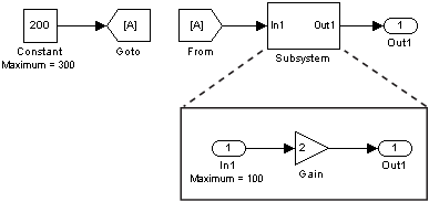
For example, consider the following model:

In this model, the Constant block specifies its Output maximum parameter as 300, and that of the Inport block is set to 100. Suppose you enable the Simulation range checking diagnostic and simulate the model. The Inport block back propagates its maximum value to the nonvirtual block that precedes it, i.e., the Constant block. Simulink then uses the smaller of the two maximum values to check the signal that the Constant block outputs. Because the Constant block outputs a signal whose value (200) exceeds the tightest range, Simulink generates an error.

Unexpected Errors or Warnings for Data with Greater Precision or Range than double

When a data item (signal or parameter) uses a data type other than double, before comparison, Simulink casts the data item and each design limit (minimum or maximum value that you specify) to the nondouble data type. This technique helps prevent the generation of unnecessary, misleading errors and warnings.

However, Simulink stores design limits as double before comparison. If the data type of the data item has higher precision than double (for example, a fixed-point data type with a 128-bit word length and a 126-bit fraction length) or greater range than double, and double cannot exactly represent the value of a design limit, Simulink can generate unexpected warnings and errors.

If the nondouble type has higher precision, consider rounding the design limit to the next number furthest from zero that double can represent. For example, suppose that a signal generates an error after you set the maximum value to 98.8847692348509014. At the command prompt, calculate the next number furthest from zero that double can represent.

format long
98.8847692348509014 + eps(98.8847692348509014)
ans =

  98.884769234850921

Use the resulting number, 98.884769234850921, to replace the maximum value.

Related Topics