Define AUTOSAR Component Behavior by Creating or Linking Models
After you add and connect software composition and component blocks in your AUTOSAR architecture model, add Simulink® behavior to the components and compositions. For each AUTOSAR software component and composition blocks, you can:
Create a model based on the block interface.
Link to an implementation model.
Create a model from an AUTOSAR XML (ARXML) component description.
To initiate these actions, select a Classic Component or Adaptive Component blocks. Place your cursor over the displayed ellipsis, and select a component model cue — Create Simulink Behavior, Link to Model, or Create Component Model from ARXML.
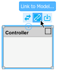
The selections open dialog boxes that help you create or link a model that defines the Simulink behavior of the component.
The creation and linking actions can be initiated in other ways, for example, from an architecture block context menu or from the toolstrip Modeling tab.
After you associate an implementation model with an AUTOSAR component, if you have Embedded Coder® software, you can use component block cues or right-click options to generate code and export ARXML files. The ARXML export uses the XML options of the parent architecture model.
When the components in an architecture model have defined behavior, you can simulate the behavior of the aggregated components. See Configure AUTOSAR Scheduling and Simulation.
Create Simulink Behavior Based on Block Interface
To create a stub implementation model and map it to an AUTOSAR software component, use the cue Create Simulink Behavior on the Classic Component or Adaptive Component.
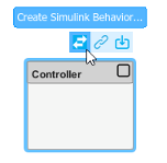
Clicking the cue creates a model based on the interface of the authored component. Ports that you created on the software component block are present in the implementation model.
This example describes how to create Simulink behavior for a classic architecture component. The workflow for creating behavior for an adaptive component is the same.
Create or open an architecture model. To create a model, open the Simulink Start Page. Under AUTOSAR Blockset, open the Software Architecture template.
From the Modeling tab, in the Platform section, confirm that the AUTOSAR platform is correct. For this example, select
Classic Platform.From the Modeling tab or the palette to the left of the canvas, add a Classic Component block to the model and name it
Controller. The Property Inspector displays the component Kind property asApplication, which is correct for this component.Click the block edges to add require (input) ports named
APP_PercentandTPS_Percentand a provide (output) port namedThrCmd_Percent. (For a controller component with the same naming, see the example Author AUTOSAR Compositions and Components in Architecture Model.)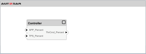
From the Modeling tab, click Functions Editor (System Composer). You can use the Functions Editor to author and schedule component runnables. For more information, see Author and Extend Functions for Software Architectures (System Composer).
Select the
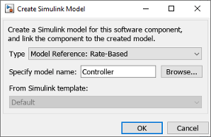
Controllerblock, place your cursor over the displayed ellipsis, and select cue Create Simulink Behavior. A model creation dialog box opens.Enter the type of model reference, periodic-rate runnable (
Rate-Based) or function-call runnable (Export-Function). For more information about modeling patterns, see Modeling Patterns for AUTOSAR Runnables.For this example, to create behavior for a classic architecture component, select
Rate-Based.Enter a name for the new model or accept the block name default.
Select a custom Simulink template for the new model or accept the default, a blank template. For more information about creating your own Simulink templates, see Create Template from Model.
To create a stub implementation model and map it to the AUTOSAR
Controllercomponent, click OK.Model
Controller.slxis created in the working folder.To view the initial model content, open the
Controllerblock. The ports are stubbed with Ground and Terminator blocks so that the model can immediately be updated and simulated.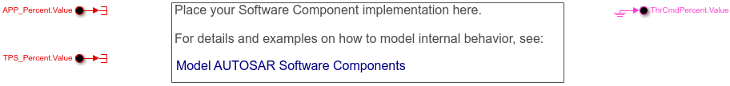
In the open
Controllermodel, to view the model mapping and dictionary, open the AUTOSAR Component Designer app. This view shows the mapping and properties of the model portAPP_Percent.Value. The model port maps to AUTOSAR component portAPP_Percent.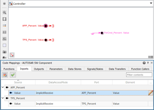
To view and modify additional AUTOSAR properties for the currently-selected element, click the
 icon.
icon.After creating the stub model representation of the AUTOSAR component, use Simulink tools to develop the component implementation. You refine the AUTOSAR configuration and create algorithmic model content. For an example
Controllerblock implementation, see the modelautosar_tpc_controllerprovided with example Author AUTOSAR Compositions and Components in Architecture Model.
Link to Implementation Model
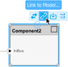
To reference an existing Simulink implementation model from an AUTOSAR software component, use the block cue Link to Model for the Classic Component or Adaptive Component block. Clicking the cue initiates linking of the component block to an implementation model that you specify. By linking to existing models, you can deploy verified implementation models in your AUTOSAR design without requalification.
The implementation model must meet model linking requirements. The model must:
Use the same AUTOSAR target as the architecture model.
Have a complete mapping of Simulink model elements to AUTOSAR component elements.
Implement root-level ports with In Bus Element and Out Bus Element blocks instead of Inport and Outport blocks.
Use a fixed-step solver.
Map to an AUTOSAR software component that is not already mapped to a different model in the composition hierarchy.
If the specified implementation model meets the linking requirements, the software links the component block to the model and updates the block and model interfaces to match.
If the implementation model does not meet one or more of the linking requirements, the software opens the AUTOSAR Model Linker app, which offers fixes for the unmet requirements. For example, if an implementation model uses root Inport and Outport blocks, the app offers to fix the issue by converting the signal ports to bus ports. When you click Fix All, the software fixes the unmet requirements and finishes linking the component block to the model.
This example describes how to link an AUTOSAR classic component to an existing implementation model. The workflow for linking an adaptive component to an implementation model is the same.
Create or open an architecture model. To create a model, open the Simulink Start Page. Under AUTOSAR Blockset, open the Software Architecture template.
From the Modeling tab, in the Platform section, confirm that the AUTOSAR platform is correct. For this example, select
Classic Platform.From the Modeling tab or the palette, add a Classic Component block to the model. The Property Inspector displays the component Kind property as
Application, which is correct for this component.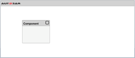
Link the
Componentblock to an implementation model that is not already configured for architecture model use. For example, select a model that is not configured for AUTOSAR or uses signal ports instead of bus ports at the root level. This example uses theswcmodel.openExample('swc')Select the
Componentblock, place your cursor over the displayed ellipsis, and select cue Link to Model. In the Link to Model dialog box, browse to the implementation modelswc.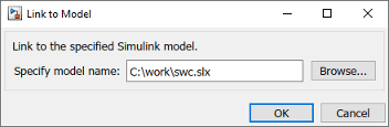
To reference the implementation model from the AUTOSAR
Componentcomponent, click OK.If the specified implementation model does not meet one or more of the linking requirements, the software opens the AUTOSAR Model Linker app, which offers fixes for the unmet requirements.
Observe the linking requirements for
swc.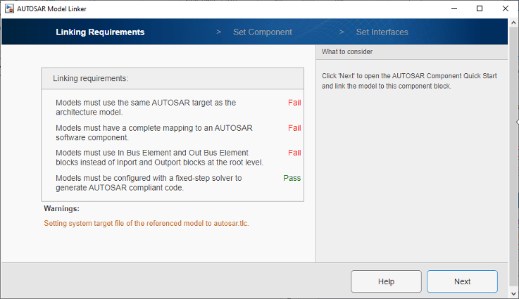
If the Linking Requirements pane displays a Fix All button, you are ready to fix the unmet linking requirements and link the component block to the implementation model. Click Fix All.
If the implementation model does not have a complete AUTOSAR component mapping, as in this example, you must map the model before linking. Click Next and work through mapping panes Set Component and Set Interfaces. For more information, see Create AUTOSAR Software Component in Simulink. When you complete the Set Interfaces pane, click Fix All.
Simulink links the Component block to model
swcand updates the block interface to match the model implementation.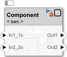
To view the model content, open the
Componentblock. In the openComponentmodel, to view the model mapping and dictionary, open the AUTOSAR Component Designer app.After linking the AUTOSAR component to the implementation model, you can connect the component block to other blocks or root ports in the design.
Create Model from ARXML Component Description
To create an AUTOSAR implementation model from an ARXML component description and map it to an AUTOSAR software component, use the block cue Create Component Model from ARXML for the Classic Component block or the Adaptive Component block.
Clicking the cue creates a model based on a specified ARXML description, links the component block to the model, and updates the block and model interfaces to match.
This example describes how to create an AUTOSAR classic model based on a specified ARXML description. The workflow is the same for creating an adaptive model from ARXML.
Create or open an architecture model. To create a model, open the Simulink Start Page. Under AUTOSAR Blockset, open the Software Architecture template.
From the Modeling tab, in the Platform section, confirm that the AUTOSAR platform is correct. For this example, select
Classic Platform.From the Modeling tab or from the palette, add a Classic Component block to the model and name it
Controller. The Property Inspector displays the component Kind property asApplication, which is correct for this component.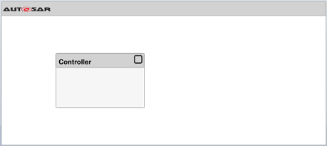
The example Import AUTOSAR XML Descriptions Into Simulink provides an ARXML file that includes a controller component description. The ARXML file is on the default MATLAB® search path. Open the ARXML file using this MATLAB command:
openExample('autosarblockset/ImportAUTOSARComponentToSimulinkExample',...
'supportingfile','ThrottlePositionControlComposition.arxml');
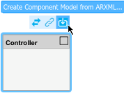
Select the
Controllerblock, place your cursor over the displayed ellipsis, and select cue Create Component Model from ARXML. The AUTOSAR Importer App opens.Work through the import and model creation procedure.
In the Select ARXML pane, browse to one or more AUTOSAR XML files that provide one or more software component descriptions. This example uses a file copied in an earlier step,
ThrottlePositionControlComposition.arxml. To import the description, click Next.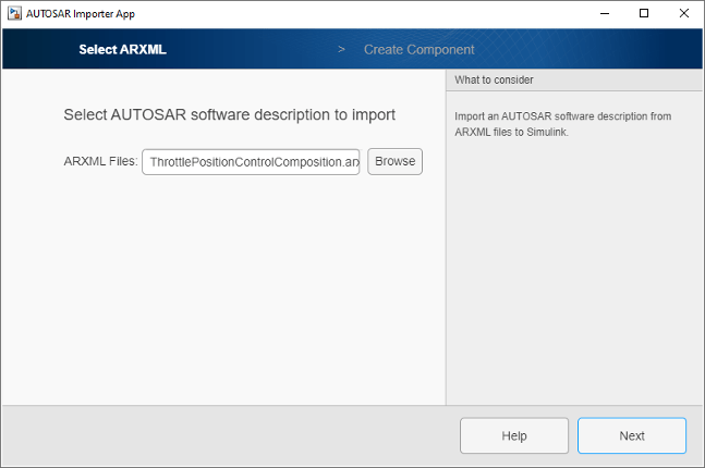
In the Create Component pane, select the software component from which to create a model. From the list of components imported in the previous step, this example selects
Controller.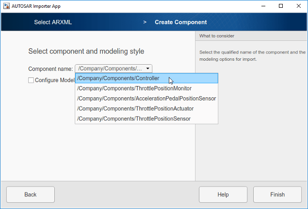
To view optional settings for model creation, select Configure Modeling Options.
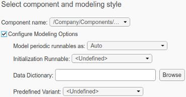
You can:
Model periodic runnables as atomic subsystems or function-call subsystems, or accept a default modeling style selection (
Auto).Select an existing AUTOSAR runnable as the initialization runnable for the component. In this example,
Controller_Initis available for selection.Specify a Simulink data dictionary into which to import data objects corresponding to AUTOSAR data types in the XML file. If the specified dictionary does not already exist, the importer creates it. The model is then associated with the data dictionary.
Select an AUTOSAR
PredefinedVariantdefined in the AUTOSAR XML file to initializeSwSystemconstdata that serves as input to control variation points. For more information, see Control AUTOSAR Variants with Predefined Value Combinations. In this example, noPredefinedVariantis available for selection.
For more information about model creation options and behavior, see
createComponentAsModel.To create the model and map it to the AUTOSAR
Controllercomponent, click Finish. Simulink creates modelController.slxin the working folder and updates the block interface to match the model implementation.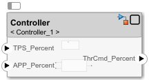
To view the model content, open the
Controllerblock. In the openControllermodel, to view the model mapping and dictionary, open the AUTOSAR Component Designer app.After creating the AUTOSAR implementation model and linking the AUTOSAR component to it, connect the component block to other blocks or root ports in the design. For a fully connected controller component, see example Author AUTOSAR Compositions and Components in Architecture Model.
See Also
Classic Component | createComponentAsModel
Topics
- Configure AUTOSAR Scheduling and Simulation
- Author AUTOSAR Compositions and Components in Architecture Model
- Configure AUTOSAR Ports By Using Simulink Bus Ports
- Import AUTOSAR XML Descriptions Into Simulink
- Control AUTOSAR Variants with Predefined Value Combinations
- Configure AUTOSAR Architecture Model Programmatically