Configure AUTOSAR Client-Server Communication
In Simulink®, you can model AUTOSAR client-server communication for simulation and code generation. For information about the Simulink blocks you use and the high-level workflow, see Client-Server Interface.
To model AUTOSAR servers and clients, you can do either or both of the following:
Import AUTOSAR servers and clients from ARXML code into a model.
Configure AUTOSAR servers and clients from Simulink blocks.
This topic provides examples of AUTOSAR server and client configuration that start from Simulink blocks.
Configure AUTOSAR Server
This example shows how to configure a Simulink Function block as an AUTOSAR server.
Open the relevant supporting files by entering the following commands at the MATLAB® command line:
openExample("mControllerWithInterface_server.slx")Open a model in which you want to create and configure an AUTOSAR server, or open the example model
mControllerWithInterface_server.slx.Add a Simulink Function block to the model. The example model provides two Simulink Function blocks,
doOverrideandreadData.
Configure the Simulink Function block to implement a server function. Configure a function prototype and implement the server function algorithm.
In the example model, the contents of the Simulink Function block named
readDataimplement a server function namedreadData.
The contents include:
Trigger block
readData, representing a trigger port for the server function. For the Trigger block:Trigger type is set to
function-call.Treat as Simulink function is selected.
Function visibility is set to
global.
Argument Inport block
Opand Argument Outport blocksData,ERR, andNegCode, corresponding to the function prototype[Data,ERR,NegCode]=readData(Op).Note
When configuring server function arguments, you must specify signal data type, port dimensions, and signal type on the Signal Attributes tab of the inport and outport blocks. The AUTOSAR configuration fails validation if signal attributes are absent for server function arguments.
Blocks implementing the
readDatafunction algorithm.In this example, a few simple blocks provide
Data,ERR, andNegCodeoutput values with minimal manipulation. A Constant block represents the value of an application error defined for the server function. The value ofOppassed by the caller is ignored. In a real-world application, the algorithm could perform a more complex manipulation, for example, selecting an execution path based on the passed value ofOp, producing output data required by the application, and checking for error conditions.
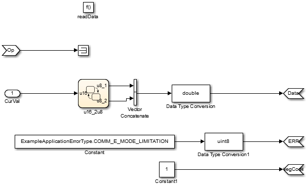
When the server function is working in Simulink, set up the Simulink Function block in a model configured for AUTOSAR.
For example, configure the current model for AUTOSAR or copy the block into an AUTOSAR model.
The example model is an AUTOSAR model, into which the Simulink Function block
readDatahas been copied. In place of a meaningfulOpinput value for thereadDatafunction, Simulink data transfer lineCurValprovides an input value that is used in the function algorithm.
Be aware that if your AUTOSAR model contains multiple instances of server components and is configured to generate reusable code, code generation is supported but simulation is not. Simulation of multi-instance AUTOSAR models that contain global Simulink Function blocks is not supported.
Configure required elements for your AUTOSAR server.
The required elements to configure an AUTOSAR server, in the general order they are created, are:
AUTOSAR client-server (C-S) interface
One or more AUTOSAR operations for which the C-S interface handles client requests
AUTOSAR server port to receive client requests for a server operation
For each server operation, an AUTOSAR server runnable to execute client requests
Open the AUTOSAR Dictionary. To view AUTOSAR Client-Server interfaces in the model, go to the C-S Interfaces view. The example model already contains a client-server interface.

If a C-S interface does not yet exist in your model, create one.
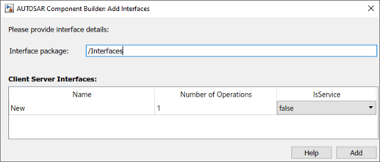
In the C-S interfaces view, click the Add button
 . This action opens the Add Interfaces
dialog box.
. This action opens the Add Interfaces
dialog box.In the dialog box, name the new C-S Interface, and specify the number of operations you intend to associate with the interface. Leave other parameters at their defaults. Click Add. The new interface appears in the C-S interfaces view.
Under C-S Interfaces, create one or more AUTOSAR server operations for which the C-S interface handles client requests. Each operation corresponds to a Simulink server function in the model.
Expand C-S Interfaces and expand the individual C-S interface to which you want to add a server operation. (In the example model, expand
CsIf1.) To view operations for the interface, select Operations. The example model already contains AUTOSAR server operations nameddoOverrideandreadData.
If a server operation does not yet exist in your model, create one. (If your C-S interface contains a placeholder operation named
Operation1, you can safely delete it.)In the operations view, click the Add button
 . This action opens the Add Operation
dialog box.
. This action opens the Add Operation
dialog box.In the dialog box, enter the Operation Name. Specify the name of the corresponding Simulink server function.
If the corresponding Simulink server function has arguments, select the function in the Simulink Function list. This action causes AUTOSAR operation arguments to be automatically created based on the Simulink server function arguments. Click OK. The operation and its arguments appear in the operations view.

Examine the arguments listed for the AUTOSAR server operation. Expand Operations, expand the individual operation (for example,
readData), and select Arguments. The listed arguments correspond to the Simulink server function prototype.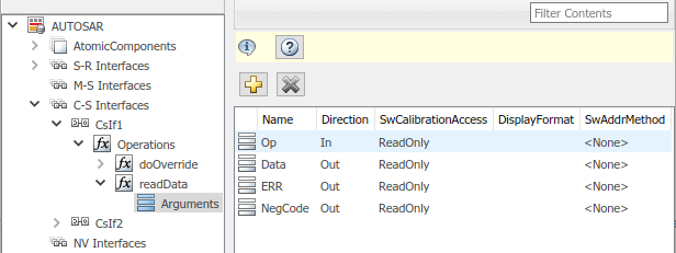
To view AUTOSAR server ports in the model, go to the server ports view. Expand AtomicComponents, expand the individual component that you are configuring, and select ServerPorts. The example model already contains an AUTOSAR server port named
sPort.
If a server port does not yet exist in your model, create one.
In the server ports view, click the Add button
 . This action opens the Add Ports
dialog box.
. This action opens the Add Ports
dialog box.In the dialog box, name the new server port, and select the C-S interface for which you configured a server operation. Click Add. The new port appears in the server ports view.

For each AUTOSAR server operation, configure an AUTOSAR server runnable to execute client requests. To view AUTOSAR runnables in the model, select Runnables. The example model already contains a server runnable for
readData, namedRunnable_readData.If a suitable server runnable does not yet exist in your model, create one.
In the runnables view, click the Add button
 . This action adds a table entry for a
new runnable.
. This action adds a table entry for a
new runnable.Select the new runnable and configure its name and symbol. (In the example model, the symbol name for
Runnable_readDatais the function namereadData.)Create an operation-invoked event to trigger the server runnable. (The example model defines event
event_readDatafor server runnableRunnable_readData.)Under Events, click Add Event. Select the new event.
For Event Type, select
OperationInvokedEvent.Enter the Event Name.
Under Event Properties, select a Trigger value that corresponds to the server port and C-S operation previously created for the server function. (In the example model, the Trigger value selected for
Runnable_readDataissPort.readData, combining server portsPortwith operationreadData.) Click Apply.

This step completes the configuration of an AUTOSAR server in the AUTOSAR Dictionary view of the configuration.
Switch to the Code Mappings editor view of the configuration and map the Simulink server function to the AUTOSAR server runnable.
Open the Code Mappings editor. Select the Functions tab.
Select the Simulink server function. To map the function to an AUTOSAR runnable, click on the Runnable field and select the corresponding runnable from the list of available server runnables. In the example model, the Simulink function
readDatais mapped to AUTOSAR runnableRunnable_readData.
To validate the AUTOSAR component configuration, click the Validate button
 . If errors are reported, fix the errors, and
retry validation. Repeat until validation succeeds.
. If errors are reported, fix the errors, and
retry validation. Repeat until validation succeeds.Generate C and ARXML code for the model.
After you configure an AUTOSAR server, configure a corresponding AUTOSAR client invocation, as described in Configure AUTOSAR Client.
Configure AUTOSAR Client
After you configure an AUTOSAR server, as described in Configure AUTOSAR Server, configure a corresponding AUTOSAR client
invocation. This example shows how to configure a Function
Caller block as an AUTOSAR client invocation. The example uses the example
model mControllerWithInterface_client.slx.
Open a model in which you want to create and configure an AUTOSAR client, or open the example model
mControllerWithInterface_client.slx.openExample('mControllerWithInterface_client');Add a Function Caller block to the model. The example model provides a Simulink Function block named
readData, which is located insideRunnable3_Subsystem.
Configure the Function Caller block to call a corresponding Simulink Function block. Double-click the block to open it, and edit the block parameters to specify the server function prototype.
In the example model, the
readDataFunction Caller parameters specify a function prototype for thereadDataserver function used in the AUTOSAR server example, Configure AUTOSAR Server. Here is thereadDatafunction from the server example.
The Function Caller parameters include function prototype and argument specification fields. The function name in the prototype must match the Operation Name specified for the corresponding server operation. See the operation creation step in Configure AUTOSAR Server. The argument types and dimensions also must match the server function arguments.

Note
If you want to simulate the function invocation at this point, you must place the Function Caller block in a common model or test harness with the corresponding Simulink Function block. Simulation is not required for this example.
When the function invocation is completely formed in Simulink, set up the Function Caller block in a model configured for AUTOSAR. For example, configure the current model for AUTOSAR or copy the block into an AUTOSAR model.
Tip
If you create (or copy) a Function Caller block in a model before you map and configure the AUTOSAR component, you have the option of having the software populate the AUTOSAR operation arguments for you, rather than creating the arguments manually. To have the arguments created for you, along with a fully-configured AUTOSAR client port and a fully mapped Simulink function caller, use the AUTOSAR Component Quick Start to create a default component. For more information, see Create AUTOSAR Software Component in Simulink.
The example model is an AUTOSAR model, into which the Function Caller block
readDatahas been copied. The block is connected to inports, outports, and signal lines matching the function argument data types and dimensions.
Note
Whenever you add or change a Function Caller block in an AUTOSAR model, update function callers in the AUTOSAR configuration. Open the Code Mappings editor. In the dialog box, click the Update button
 . This action loads or updates Simulink data transfers, function callers, and numeric types in your
model. After updating, the function caller you added appears in the
Function Callers tab of the Code Mappings
editor.
. This action loads or updates Simulink data transfers, function callers, and numeric types in your
model. After updating, the function caller you added appears in the
Function Callers tab of the Code Mappings
editor.The required elements to configure an AUTOSAR client, in the general order they should be created, are:
AUTOSAR client-server (C-S) interface
One or more AUTOSAR operations matching the Simulink server functions that you defined in the AUTOSAR server model
AUTOSAR client port to receive client requests for a server operation offered by the C-S interface
Open the AUTOSAR Dictionary. To view AUTOSAR C-S interfaces in the model, go to the C-S Interfaces view. The example model already contains a client-server interface named
csInterface.
If a C-S interface does not yet exist in the AUTOSAR configuration, create one.
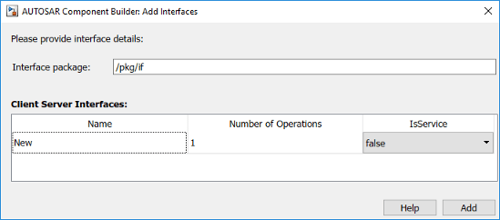
In the C-S interfaces view, click the Add button
 . This action opens the Add Interfaces
dialog box.
. This action opens the Add Interfaces
dialog box.In the dialog box, name the new C-S Interface, and specify the number of operations you intend to associate with the interface. Leave other parameters at their defaults. Click Add. The new interface appears in the C-S interfaces view.
Under C-S Interfaces, create one or more AUTOSAR operations matching the Simulink server functions that you defined in the AUTOSAR server model.
Expand C-S Interfaces and expand the individual C-S interface to which you want to add an AUTOSAR operation. (In the example model, expand
CsInterface.) To view operations for the interface, select Operations. The example model already contains an AUTOSAR operation namedreadData.
If an AUTOSAR operation does not yet exist in your model, create one. (If your C-S interface contains a placeholder operation named
Operation1, you can safely delete it.)In the operations view, click the Add button
 . This action opens the Add Operation
dialog box.
. This action opens the Add Operation
dialog box.In the dialog box, enter the Operation Name. Specify the name of the corresponding Simulink server function. Leave Simulink Function set to
None, because the client model does not contain the Simulink server function block. Click OK. The new operation appears in the operations view.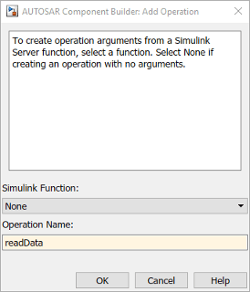
Add the AUTOSAR operation arguments.
Expand Operations, expand the individual operation (for example,
readData), and select Arguments.In the arguments view, click the Add button
 one time for each function argument.
For example, for
 readData, click the Add button four times, for argumentsOp,Data,ERR, andNegCode. Each click creates one new argument entry.Select each argument entry and set the argument Name and Direction to match the function prototype.

To view AUTOSAR client ports in the model, go to the client ports view. Expand AtomicComponents, expand the individual component that you are configuring, and select ClientPorts. The example model already contains an AUTOSAR client port named
cPort.
If a client port does not yet exist in your model, create one.
In the client ports view, click the Add button
 . This action opens the Add Ports
dialog box.
. This action opens the Add Ports
dialog box.In the dialog box, name the new client port, and select a C-S interface. Click Add. The new port appears in the client ports view.

This step completes the configuration of an AUTOSAR client in the AUTOSAR Dictionary view of the configuration.
Switch to the Code Mappings editor view of the configuration and map the Simulink function caller to an AUTOSAR client port and C-S operation.
Open the Code Mappings editor. Select the Function Callers tab.
Select the Simulink function caller. Click on the ClientPort field and select a port from the list of available AUTOSAR client ports. Click on the Operation field and select an operation from the list of available AUTOSAR C-S operations. In the example model, the Simulink function caller
readDatais mapped to AUTOSAR client portcPortand C-S operationreadData.
To validate the AUTOSAR component configuration, click the Validate button
 . If errors are reported, fix the errors, and
retry validation. Repeat until validation succeeds.
. If errors are reported, fix the errors, and
retry validation. Repeat until validation succeeds.Generate C and ARXML code for the model.
Configure AUTOSAR Client-Server Error Handling
AUTOSAR defines an application error status mechanism for client-server error handling. An AUTOSAR server returns error status, with a value matching a predefined possible error. An AUTOSAR client receives and responds to the error status. An AUTOSAR software component that follows client-server error handling guidelines potentially provides error status to AUTOSAR Basic Software, such as a Diagnostic Event Manager (DEM).
In Simulink, you can:
Import ARXML code that implements client-server error handling.
Configure error handling for a client-server interface.
Generate C and ARXML code for client-server error handling.
If you import ARXML code that implements client-server error handling, the importer creates error status ports at the corresponding server call-point (Function Caller block) locations.
To implement AUTOSAR client-server error handling in Simulink:
Define the possible error status values that the AUTOSAR server returns in a Simulink data type. Define one or more error codes in the range 0-63, inclusive. The underlying storage of the data type must be an unsigned 8-bit integer. The data scope must be
Exported. For example, define an enumeration typeappErrType:classdef(Enumeration) appErrType < uint8 enumeration SUCCESS(0) ERROR(1) COMM_MODE_LIMITATION(2) OVERFLOW(3) UNDERFLOW(4) VALUE_MOD3(5) end methods (Static = true) function descr = getDescription() descr = 'Definition of application error type.'; end function hdrFile = getHeaderFile() hdrFile = ''; end function retVal = addClassNameToEnumNames() retVal = false; end function dataScope = getDataScope() dataScope = 'Exported'; end end endNote
The Simulink data type that you define to represent possible errors in the model does not directly impact the AUTOSAR possible errors that are imported and exported in ARXML code. To modify the exported possible errors for a C-S interface or C-S operation, use AUTOSAR properties functions. This topic provides examples.
Define an error status output argument for the Simulink Function block that models the AUTOSAR server. Configure the error status argument as the only function output or add it to other outputs. For example, here is a Simulink Function block that returns an error status value in output
err.
The Simulink Function block implements an algorithm to return error status.

Reference the possible error values type in the model. In the Argument Outport block parameters for the error outport, specify the error status data type, in this case,
appErrType. Set Port dimensions to 1 and Signal type toreal.
Configure the AUTOSAR properties of the error argument in the client-server interface. Open the AUTOSAR Dictionary, expand C-S Interfaces, and navigate to the Arguments view of the AUTOSAR operation. To add an argument, click the Add button
 . Configure the argument name and set
Direction to
 Error.
Create an error port in each Function Caller block that models an AUTOSAR client invocation. For example, here is a Function Caller block that models an invocation of
fcnWErr.
In the Function Caller block parameters, specify the same error status data type.

Configure the AUTOSAR properties of the error argument to match the information in the AUTOSAR Dictionary, Arguments view, shown in Step 4.
The generated C code for the function reflects the configured function signature and the logic defined in the model for handling the possible errors.
appErrType fcnWErr(real_T x1, real_T x2)
{
  appErrType rty_err_0;
  if (...) == 0.0) {
    rty_err_0 = ...;
  } else {
    rty_err_0 = ...;
  }

  return rty_err_0;
}
Additionally, for the enumeration type class definition used in this example, the
build generates header file appErrType.h, containing the possible
error type definitions.
The exported ARXML code contains the possible error definitions, and references to them.
<POSSIBLE-ERRORS>
   <APPLICATION-ERROR …>
      <SHORT-NAME>SUCCESS</SHORT-NAME>
      <ERROR-CODE>0</ERROR-CODE>
   </APPLICATION-ERROR>
   <APPLICATION-ERROR …>
      <SHORT-NAME>ERROR</SHORT-NAME>
      <ERROR-CODE>1</ERROR-CODE>
   </APPLICATION-ERROR>
   …
   <APPLICATION-ERROR …>
      <SHORT-NAME>UNDERFLOW</SHORT-NAME>
      <ERROR-CODE>4</ERROR-CODE>
   </APPLICATION-ERROR>
   <APPLICATION-ERROR …>
      <SHORT-NAME>VALUE_MOD3</SHORT-NAME>
      <ERROR-CODE>5</ERROR-CODE>
   </APPLICATION-ERROR>
</POSSIBLE-ERRORS>
You can use AUTOSAR property functions to programmatically modify the possible errors
that are exported in ARXML code, and to set the Direction property
of a C-S operation argument to Error.
The following example adds UNDERFLOW and VALUE_MOD3 to the possible errors for a C-S
interface named fcnWErr.
>> arProps = autosar.api.getAUTOSARProperties(bdroot)
>> get(arProps,'fcnWErr','PossibleError')
ans =
    'fcnWErr/SUCCESS'    'fcnWErr/ERROR'    'fcnWErr/COMM_MODE…'
    'fcnWErr/OVERFLOW'
>> get(arProps,'fcnWErr/OVERFLOW','errorCode')
ans =
           3
>> add(arProps,'fcnWErr','PossibleError','UNDERFLOW')
>> set(arProps,'fcnWErr/UNDERFLOW','errorCode',4)
>> add(arProps,'fcnWErr','PossibleError','VALUE_MOD3')
>> set(arProps,'fcnWErr/VALUE_MOD3','errorCode',5)
>> get(arProps,'fcnWErr','PossibleError')
ans =
    'fcnWErr/SUCCESS'    'fcnWErr/ERROR'    'fcnWErr/COMM_MODE…'
    'fcnWErr/OVERFLOW'    'fcnWErr/UNDERFLOW'    'fcnWErr/VALUE_MOD3'
You can also access possible errors on a C-S operation. The following example lists
possible errors for operation fcnWErr on C-S interface
fcnWErr.
>> arProps = autosar.api.getAUTOSARProperties(bdroot)
>> get(arProps,'fcnWErr/fcnWErr','PossibleError')
ans =
    'fcnWErr/SUCCESS'    'fcnWErr/ERROR'    'fcnWErr/COMM_MODE…'
    'fcnWErr/OVERFLOW'
The following example sets the direction of C-S operation argument
err to Error.
>> arProps = autosar.api.getAUTOSARProperties(bdroot)
>> set(arProps,'fcnWErr/fcnWErr/err','Direction','Error')
>> get(arProps,'fcnWErr/fcnWErr/err','Direction')
ans =
    Error
Concurrency Constraints for AUTOSAR Server Runnables
The following blocks and modeling patterns are incompatible with concurrent execution of an AUTOSAR server runnable.
Blocks that are inside a Simulink® function:
Blocks with state, such as Unit Delay
Blocks with zero-crossing logic, such as Triggered Subsystem and Enabled Subsystem
Stateflow® charts
Other Simulink Function blocks
Noninlined subsystems
Legacy C function calls with side effects
Modeling patterns inside a Simulink® function:
Writing to a data store memory (for example, per-instance-memory)
Writing to a global block signal (for example, static memory)
To enforce concurrency constraints for AUTOSAR server runnables, use the runnable property canBeInvokedConcurrently. The property is located in the Runnables view in the AUTOSAR Dictionary.
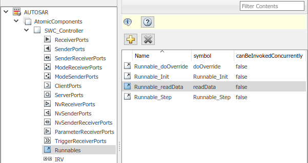
When canBeInvokedConcurrently is set to true for a server runnable, AUTOSAR validation checks for blocks and modeling patterns that are incompatible with concurrent execution of a server runnable. If a Simulink® function contains an incompatible block or modeling pattern, validation reports errors. If canBeInvokedConcurrently is set to false, validation does not check for blocks and modeling patterns that are incompatible with concurrent execution of a server runnable.
You can set canBeInvokedConcurrently to true only for an AUTOSAR server runnable — that is, a runnable with an OperationInvokedEvent. The property canBeInvokedConcurrently is not supported for runnables with other event triggers, such as timing events. If canBeInvokedConcurrently is set to true for a nonserver runnable, AUTOSAR validation fails.
To programmatically set the runnable property canBeInvokedConcurrently, use the AUTOSAR property function set. The following example sets the runnable property canBeInvokedConcurrently to true for an AUTOSAR server runnable named Runnable_readData.
open_system("mControllerWithInterface_server")
arProps = autosar.api.getAUTOSARProperties("mControllerWithInterface_server");
SRPath = find(arProps,[],"Runnable","Name","Runnable_readData")
SRPath = 1×1 cell array
    {'SWC_Controller/ControllerWithInterface_ar/Runnable_readData'}
invConc = get(arProps,"SWC_Controller/ControllerWithInterface_ar/Runnable_readData",...
  "canBeInvokedConcurrently")
invConc = logical
   0
set(arProps,"SWC_Controller/ControllerWithInterface_ar/Runnable_readData",...
  "canBeInvokedConcurrently",true)
invConc = get(arProps,"SWC_Controller/ControllerWithInterface_ar/Runnable_readData",...
  "canBeInvokedConcurrently")
invConc = logical
   1
See Also
Simulink Function | Function Caller | Trigger | Argument Inport | Argument Outport