Model AUTOSAR Component Behavior
In Simulink®, you can model AUTOSAR component behavior, including behavior of runnables, events, and inter-runnable variables.
AUTOSAR Elements for Modeling Component Behavior
To model AUTOSAR component behavior, you model AUTOSAR elements that describe scheduling and resource sharing aspects of a component. The AUTOSAR elements that bear on component behavior include:
Runnables and the events to which they respond
Inter-runnable variables, used to communicate data between runnables in the same component
Included data type sets, which provide component internal data types
System constants, used to specify system-level constant values that are available for reference in component algorithms
Per-instance memory, used to specify instance-specific global memory within a component
Static and constant memory, for access to global data and parameter values within a component
Shared and per-instance parameters, for access to component internal parameter data
Port parameters, for port-based access to parameter data
This topic describes how to model the AUTOSAR elements that help you define component behavior.
Runnables
AUTOSAR software components contain runnables that are directly or indirectly scheduled by the underlying AUTOSAR operating system.
This figure shows an AUTOSAR software component with two runnables, Runnable
1 and Runnable 2. RTEEvents, events generated by the AUTOSAR
Runtime Environment (RTE), trigger each runnable. For example, TimingEvent is an RTEEvent
that is generated periodically.

A component also can contain a single runnable, represented by a model, and can be single-rate or multirate.
Note
The software generates an additional runnable for the initialization function regardless of the modeling pattern.
For more information, see Configure AUTOSAR Runnables and Events.
Inter-Runnable Variables
In AUTOSAR, inter-runnable variables are used to communicate data
between runnables in the same component. You define these variables in a Simulink model by the signal lines that connect subsystems (runnables). For example, in
the following figure, irv1, irv2,
irv3, and irv4 are inter-runnable variables.
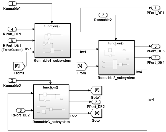
You can specify the names and data access modes of the inter-runnable variables that you export.
Included Data Type Sets
In an AUTOSAR software component model, you can import and export an ARXML description
of an AUTOSAR included data type set (IncludedDataTypeSet). An
IncludedDataTypeSet is defined as part of the internal behavior of a
software component. It contains references to AUTOSAR data type definitions that are
internal to a component and not present in the component interface descriptions. The
referenced internal data type definitions can be shared among multiple software components,
as described in Import AUTOSAR Data Types and Shared Elements to Simulink.
If you import ARXML files that contain an IncludedDataTypeSet
description into Simulink, the importer creates internal data types in the AUTOSAR component model and
maps them to header file Rte_Type.h.
In an AUTOSAR component model, to configure internal data types for export in an ARXML
IncludedDataTypeSet description, map the internal data types to header
file Rte_Type.h. Building the component model:
Exports an ARXML
IncludedDataTypeSetdescription for internal data types that are used in the model code.Generates
Rte_Type.hheader file entries for the internal data types.
For AUTOSAR IncludedDataTypeSet export, Simulink supports these data types:
Numeric
Alias
Bus
Fixed-point
Enumerated
Literal prefixes for enumeration literals are handled differently between imported and
created IncludedDataTypeSets:
If you import an
IncludedDataTypeSetthat defines aLiteralPrefixas a common prefix for enumeration literals, the importer preserves theLiteralPrefixfor export and round trip of theIncludedDataTypeSet.If you configure internal data types in a component model for export in an AUTOSAR
IncludedDataTypeSet, the exporter generates the data types in anIncludedDataTypeSetwith an emptyLiteralPrefix.
For more information, see Configure Internal Data Types for AUTOSAR IncludedDataTypeSets.
System Constants
AUTOSAR system constants (SwSystemConstants) specify system-level
constant values that are available for reference in component algorithms. To add AUTOSAR
system constants to your model, you can:
Import them from ARXML files.
Create them in the Architectural Data section of Simulink data dictionaries with an AUTOSAR Classic Platform mapping.
Although it is not recommended, you can create system constants in Simulink by using
AUTOSAR.Parameterobjects that have Storage class set toSystemConstant.
You can then reference the AUTOSAR system constants in Simulink algorithms. For example, you can reference a system constant in a Gain block, or in a condition formula inside a variant subsystem or model reference.
When you reference an AUTOSAR system constant in your model:
Exported ARXML files contain a corresponding
SwSystemConstantand a corresponding AUTOSAR variation point proxy (VariationPointProxy) that references theSwSystemConstant. If you generate modular ARXML files, theSwSystemConstantis located inmodelname_datatype.arxmlVariationPointProxyis located inmodelname_component.arxmlGenerated C code uses the generated
VariationPointProxyin places where the model uses theSwSystemConstant.
For an example of an AUTOSAR system constant that represents a conditional value associated with variant condition logic, see Configure Variants for AUTOSAR Runnable Implementations.
Per-Instance Memory
AUTOSAR supports per-instance memory, which allows you to specify instance-specific global memory within a software component. An AUTOSAR run-time environment generator allocates this memory and provides an API through which you access this memory.
Per-instance memory can be AUTOSAR-typed or C-typed. AUTOSAR-typed per-instance memory
(arTypedPerInstanceMemory) is described using AUTOSAR data types rather
than C types. When exported in ARXML files, arTypedPerInstanceMemory
allows the use of calibration and measurement tools to monitor the global variable
corresponding to per-instance memory.
AUTOSAR also allows you to use per-instance memory as a RAM mirror for data in nonvolatile RAM (NVRAM). You can access and use NVRAM in your AUTOSAR application. For more information about modeling software component access to AUTOSAR nonvolatile memory, see Model AUTOSAR Nonvolatile Memory.
To add AUTOSAR per-instance memory to your model, you can:
Import per-instance memory definitions from ARXML files.
Create model content that represents per-instance memory.
To model arTypedPerInstanceMemory, you can use block signals,
discrete states, or data stores in your AUTOSAR model:
To use block signals and discrete states, use the Code Mappings editor, Signals/States tab, to select a signal or state and map it to
arTypedPerInstanceMemory. To view and modify AUTOSAR code and calibration attributes for the per-instance memory, click the icon.
icon.To use data stores, use the Code Mappings editor, Data Stores tab, to select a data store and map it to
arTypedPerInstanceMemory. To view and modify AUTOSAR code and calibration attributes for the per-instance memory, click the icon.
For more information, see Configure AUTOSAR Per-Instance Memory.
Static and Constant Memory
AUTOSAR supports static memory (StaticMemory) and constant memory (ConstantMemory) data. Static memory corresponds to Simulink internal global signals. Constant memory corresponds to Simulink internal global parameters. In Simulink, you can import and export ARXML descriptions of AUTOSAR static and constant memory. When exported in ARXML files, static memory and constant memory allow the use of calibration and measurement tools to monitor the internal memory data.
To model AUTOSAR static memory in Simulink, use the Code Mappings editor, Signals/States or
Data Stores tab. Select a signal, state, or data store and map it to
StaticMemory. To view and modify AUTOSAR code and calibration
attributes for the static memory, click the ![]() icon.
icon.
To model AUTOSAR constant memory in Simulink, use the Code Mappings editor, Parameters tab, to select
a parameter and map it to ConstantMemory. To view and modify
AUTOSAR code and calibration attributes for the constant memory, click the
![]() icon.
icon.
For more information, see Configure AUTOSAR Static Memory and Configure AUTOSAR Constant Memory.
Shared and Per-Instance Parameters
AUTOSAR supports shared parameters (SharedParameters) and
per-instance parameters (PerInstanceParameters) for use in software
components that are potentially instantiated multiple times. Shared parameter values are
shared among all instances of a component. Per-instance parameter values are unique and
private to each component instance.
In Simulink, you can import and export ARXML descriptions of AUTOSAR shared and per-instance parameters. When exported in ARXML files, shared and per-instance parameters enable the use of calibration and measurement tools to monitor component parameters.
To model an AUTOSAR shared parameter in Simulink, configure a model workspace parameter that is not a model argument (that is,
not unique to each instance of a multi-instance model). For example, in the Model Explorer
view of the parameter, clear the Argument property. In the Code
Mappings editor, Parameters tab, select the parameter and map it to
parameter type SharedParameter. To view and modify AUTOSAR code
and calibration attributes for the shared parameter, click the ![]() icon.
icon.
To model an AUTOSAR per-instance parameter in Simulink, configure a model workspace parameter that is a model argument (that is,
unique to each instance of a multi-instance model). For example, in the Model Explorer view
of the parameter, select the Argument property. In the Code Mappings
editor, Parameters tab, select the parameter and map it to parameter
PerInstanceParameter. To view and modify AUTOSAR code and
calibration attributes for the per-instance parameter, click the ![]() icon.
icon.
For more information, see Configure AUTOSAR Shared or Per-Instance Parameters.
Port Parameters
The AUTOSAR standard defines port-based parameters for parameter communication. AUTOSAR
parameter communication relies on a parameter software component
(ParameterSwComponent) and one or more atomic software components that
require port-based access to parameter data. The ParameterSwComponent
represents memory containing AUTOSAR parameters and provides parameter data to connected
atomic software components.
In Simulink, you can model the receiver side of AUTOSAR parameter communication. By importing ARXML descriptions or configuring a software component model, you can model:
AUTOSAR parameter receiver component, which communicates with a
ParameterSwComponentto receive parameter data.AUTOSAR parameter interface, which contains parameter data elements. The data elements map to parameter or lookup table objects in the model workspace.
AUTOSAR parameter receiver port used to communicate with the
ParameterSwComponent.
When you generate code for the AUTOSAR parameter receiver component:
The exported ARXML files contain descriptions of the parameter receiver component, parameter interface, parameter data elements, and parameter receiver port.
The generated C code contains AUTOSAR port parameter
Rtefunction calls.
At run time, the software can access the parameter data elements as port-based parameters.
Because port parameter data is scoped to the model workspace and the AUTOSAR component:
Different components can use the same parameter names without naming conflicts.
An AUTOSAR composition can contain multiple instances of a parameter receiver component, each with instance-specific port parameter data values.
For more information, see Configure AUTOSAR Port Parameters for Communication with Parameter Software Component.
See Also
Topics
- Configure AUTOSAR Runnables and Events
- Configure Variants for AUTOSAR Runnable Implementations
- Configure Internal Data Types for AUTOSAR IncludedDataTypeSets
- Configure AUTOSAR Per-Instance Memory
- Configure AUTOSAR Static Memory
- Configure AUTOSAR Constant Memory
- Configure AUTOSAR Shared or Per-Instance Parameters
- Configure AUTOSAR Port Parameters for Communication with Parameter Software Component
- AUTOSAR Component Configuration
- Specify Default Data Packaging for AUTOSAR Internal Variables