Add RF Impairments and Fading Channel Model to Bluetooth LE Waveform in an Indoor Environment
This example shows how to generate a Bluetooth® low energy (LE) waveform and distort it by adding radio frequency (RF) impairments and a fading channel model.
Using this example, you can:
Generate a Bluetooth LE waveform.
Configure and add RF impairments to the generated waveform.
Configure the parameters of Rayleigh or Rician fading channel models in an indoor test environment.
Pass the impaired Bluetooth LE waveform through the specified channel model.
Visualize the power spectrum of the generated and faded Bluetooth LE waveform.
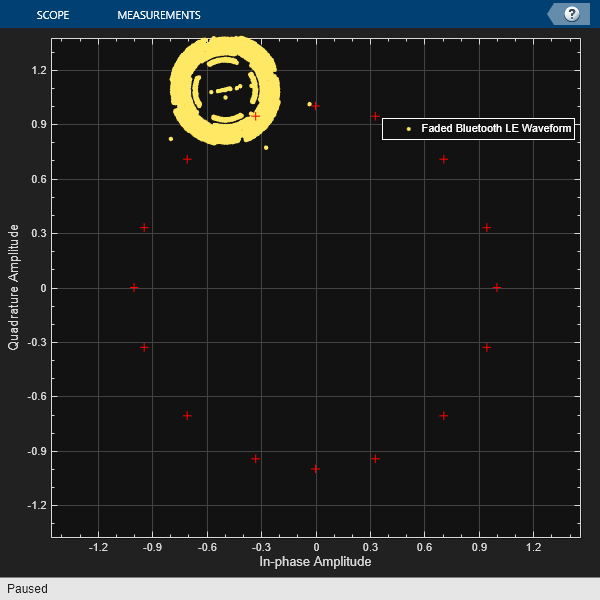
Visualize the constellation diagram of the faded Bluetooth LE waveform.
Specify the data length, in bits. The data length includes the header, payload, and cyclic redundancy check (CRC).
dataLength = 2056;
Create a message column vector of the specified data length containing random binary values.
message = randi([0 1],dataLength,1);
Specify the values of the physical layer (PHY) mode, channel index, samples per symbol, and access address.
phyMode ="LE2M"; chanIdx =
2; sps = 4; accAdd = [1 1 1 1 0 1 0 0 1 1 0 1 0 0 1 0 0 1 1 0 1 1 1 0 1 ... 0 1 0 1 1 0 0].';
Based on the specified PHY mode, set the symbol rate. Compute the sample rate by using the samples per symbol and symbol rate values.
if phyMode=="LE2M"
    symbolRate = 2e6;
else
    symbolRate = 1e6;
end
sampleRate = sps*symbolRate;
Generate the Bluetooth LE waveform from the specified configuration.
txWaveform = bleWaveformGenerator(message,Mode=phyMode,SamplesPerSymbol=sps,ChannelIndex=chanIdx,AccessAddress=accAdd);
Initialize the RF impairments for the specified PHY mode and samples per symbol by using the helperBLEImpairmentsInit helper function. The helper function returns a structure with fields for phase frequency offset, variable fractional delay, and phase noise.
initRFImpairments = helperBLEImpairmentsInit(phyMode,sps)
initRFImpairments = struct with fields:
         pfo: [1×1 comm.PhaseFrequencyOffset]
    varDelay: [1×1 dsp.VariableFractionalDelay]
      pnoise: [1×1 comm.PhaseNoise]
Specify the values of the frequency offset and phase offset.
initRFImpairments.pfo.FrequencyOffset =150; % In Hz initRFImpairments.pfo.PhaseOffset =
-1; % In degrees
Specify the values of the static timing offset, timing drift, variable timing offset, and DC offset.
staticTimingOff = 0.15*sps; timingDrift =10; % In ppm initRFImpairments.vdelay = (staticTimingOff:timingDrift:(staticTimingOff + timingDrift * (length(txWaveform) - 1)))'; initRFImpairments.dc =
4 % DC offset represents a percentage of the maximum transmitted signal
initRFImpairments = struct with fields:
         pfo: [1×1 comm.PhaseFrequencyOffset]
    varDelay: [1×1 dsp.VariableFractionalDelay]
      pnoise: [1×1 comm.PhaseNoise]
      vdelay: [8416×1 double]
          dc: 4
Add RF impairments to the generated Bluetooth LE waveform by using the helperBLEImpairmentsAddition helper function.
txImpairedWaveform = helperBLEImpairmentsAddition(txWaveform,initRFImpairments);
This example configures the channel model in an indoor test environment based on the specifications given in ITU-R M.1225 [2]. The impulse response of the fading channel is based on the tapped delay line model. The number of taps, the time delay relative to the first tap, the average power relative to the strongest tap, and the delay spread of each tap characterize the tapped delay line model. Taps are the progressively delayed components of the original waveform that are aggregated together at the receiver.
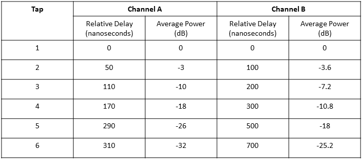
Modeling the variability of delay spread of the channel model enables you to more accurately evaluate the relative performance of the radio communication. Because you cannot capture this delay spread variability using a single tapped delay line, the ITU-R M.1225 [2] defines up to two multipath channels, channel A and channel B, for the indoor test environment. Channel A and channel B specify the low delay spread and median delay spread, respectively. This table shows the relative delay and average power for channel A and channel B corresponding to each tap.

For more information about the tapped delay line parameters, see Annex 2, Section 1.2.2 of ITU-R M.1225 [2].
Specify the number of taps.
numTaps =  5;
5;Specify the type of channel for the delay spread profile.
channelDelayProfile =  "Channel A";
Specify the channel model. Set the seed value to generate the channel model coefficient.
channelType ="Rician Channel"; seed =
10;
Specify relative delays and average power for channel A and channel B.
relativeDelaysChannelA = [0 50 110 170 290 310]*1e-9;   % In seconds
avgPowerChannelA = [0 -3 -10 -18 -26 -32];              % in dB

relativeDelaysChannelB = [0 100 200 300 500 700]*1e-9;  % In seconds
avgPowerChannelB = [0 -3.6 -7.2 -10.8 -18 -25.2];       % in dB
Based on the type of channel and taps specified, calculate path delays and average path gains for the channel model.
if channelDelayProfile == "Channel A"
    pathDelays = relativeDelaysChannelA(1:numTaps);
    avgPathGains = avgPowerChannelA(1:numTaps);

elseif channelDelayProfile == "Channel B"
    pathDelays = relativeDelaysChannelB(1:numTaps);
    avgPathGains = avgPowerChannelB(1:numTaps);
end
Specify the configuration parameters of the Rayleigh and Rician channel models.
switch channelType
    case "Rayleigh Channel"

        fadingChannel = comm.RayleighChannel(SampleRate=sampleRate, ...
            RandomStream="mt19937ar with seed", ...
            Seed=seed, ...
            AveragePathGains=avgPathGains, ...
            PathDelays=pathDelays);

    case "Rician Channel"
        fadingChannel = comm.RicianChannel(SampleRate=sampleRate, ...
            RandomStream="mt19937ar with seed", ...
            Seed=seed, ...
            AveragePathGains=avgPathGains, ...
            PathDelays=pathDelays);
end
Calculate the channel filter delay.
channelFilterDelay = info(fadingChannel).ChannelFilterDelay;
Pass the impaired Bluetooth LE waveform through the fading channel model.
txChannelWaveform = fadingChannel([txImpairedWaveform; zeros(channelFilterDelay,1)]);
txChannelWaveform = txChannelWaveform(channelFilterDelay+1:end,1);
Create a default spectrum analyzer System object™. Visualize the power spectrum of the generated and faded Bluetooth LE waveform.
scope = spectrumAnalyzer;
scope.SampleRate = sampleRate;
scope.NumInputPorts = 2;
scope.Title = "Power Spectrum of Generated and Faded Bluetooth LE Waveform";
scope.ShowLegend = true;
scope.ChannelNames = {"Generated Bluetooth LE Waveform","Faded Bluetooth LE Waveform"};
scope(txWaveform,txChannelWaveform)

Configure the reference constellation with 160 samples by using the uniquetol function. Generate a constellation diagram for the faded Bluetooth LE waveform and compare it with the reference constellation.
constellationValues = uniquetol([real(txWaveform(1:160)) imag(txWaveform(1:160))],0.01,ByRows=1);
constellationValues = constellationValues(:,1) + 1*i*constellationValues(:,2);

constellation = comm.ConstellationDiagram(Name="Constellation Diagram of the Faded Bluetooth LE Waveform",ChannelNames={"Faded Bluetooth LE Waveform"},ShowLegend=1,ReferenceConstellation=constellationValues);
constellation(txChannelWaveform)

Selected Bibliography
[1] “Bluetooth® Technology Website – The Official Website for the Bluetooth Wireless Technology. Get up to Date Specifications, News, and Development Info.” Accessed February 18, 2023. https://www.bluetooth.com/.
[2] ITU. “International Telecommunication Union, ITU-M, Recommendation M.1225 Guidelines for Evaluation of Radio Transmission Technologies for Imt-2000.” Accessed February 18, 2023. https://www.itu.int/dms_pubrec/itu-r/rec/m/R-REC-M.1225-0-199702-I!!PDF-E.pdf.
See Also
Functions
Topics
- End-to-End Bluetooth LE PHY Simulation with Multipath Fading Channel, RF Impairments, and Corrections
- End-to-End Bluetooth LE PHY Simulation Using Path Loss Model, RF Impairments, and AWGN
- End-to-End Bluetooth BR/EDR PHY Simulation with Path Loss, RF Impairments, and AWGN
- End-to-End Bluetooth LE PHY Simulation with AWGN, RF Impairments and Corrections