End-to-End Bluetooth LE PHY Simulation Using Path Loss Model, RF Impairments, and AWGN
This example uses Bluetooth® Toolbox to perform end-to-end Bluetooth low energy (LE) simulation for different Bluetooth LE physical layer (PHY) transmission modes in the presence of the path loss model, radio front-end (RF) impairments, and additive white Gaussian noise (AWGN). The simulation results show the estimated value of the bit error rate (BER), path loss, and distance between the transmitter and receiver.
Path Loss Modeling in Bluetooth LE Network
The Bluetooth Core Specifications [1] defined by the Bluetooth Special Interest Group (SIG) introduced Bluetooth LE to enable low-power short-range communication. Bluetooth LE devices operate in the globally unlicensed industrial, scientific, and medical (ISM) band in a frequency range from 2.4 GHz to 2.485 GHz. Bluetooth LE specifies a channel spacing of 2 MHz, resulting in 40 RF channels. The prominent applications of Bluetooth LE include direction finding services and building intelligent internet of things (IoT) solutions to facilitate home, commercial, and industrial automation. For more information about direction finding services in Bluetooth LE, see the Bluetooth Location and Direction Finding.
In past few years, there has been a significant increase in designing Bluetooth LE networks for a plethora of use case scenarios. To achieve high performance and quality in the Bluetooth LE network, studying the propagation of the Bluetooth LE signal along the link between the transmitter and the receiver is recommended. This example shows an end-to-end Bluetooth LE simulation considering these factors that impact the propagation of Bluetooth LE signals along the communication link between the transmitter and receiver.
Receiver sensitivity
Environment
Transmit power
Antenna gain
Receiver Sensitivity
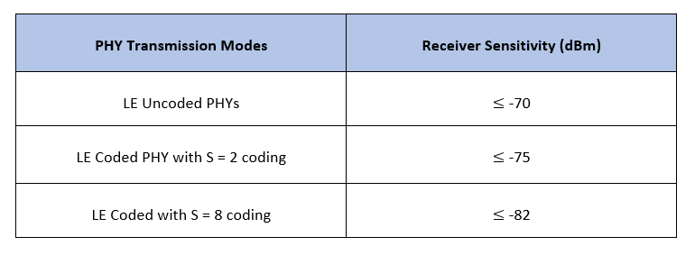
Receiver sensitivity is the measure of minimum signal strength at which the receiver can detect, demodulate, and decode the waveform. The reference sensitivity level specified in the Bluetooth Core Specifications [1] is -70 dBm. However, the actual sensitivity level for the receiver as per the Bluetooth Core Specifications [1] is defined as the receiver input level for which the BER specified in this table is achieved.
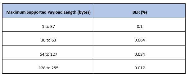
This table shows the actual sensitivity level of the receiver for a given PHY transmission mode.
Environment
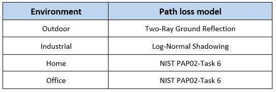
Bluetooth LE networks are operated in different environments such as home, office, industrial, and outdoor. A specific path loss model is used for each environment.
Path Loss Model
Path loss or path attenuation is the decline in the power density of a given signal as it propagates from the transmitter to receiver through space. This reduction in power density occurs naturally over the distance and is impacted by the obstacles present in the environment in which the signal is being transmitted. The path loss is generally expressed in decibels (dB) and is calculated as:
.
In this equation,
is the path loss in dB.
is the transmitted signal power in dB.
is the received signal power in dB.
Path loss models describe the signal attenuation between the transmitter and receiver based on the propagation distance and other parameters such as frequency, wavelength, path loss exponent, and antenna gains.
Free-Space Path Loss Model
Free-space path loss is the attenuation of signal strength between the transmitter and receiver along the line of sight (LoS) path through free space (usually air), excluding the effect of the obstacles in the path. The free-space path loss is calculated as:
.
In this equation,
is the distance between the transmitter and receiver.
is the signal wavelength.
Log-Normal Shadowing Path Loss Model
A log-distance path loss model reflects the path loss that a signal encounters in an indoor environment such as a building. The log-normal shadowing model [3] is an extension of log-distance path loss model. Unlike the log-distance model, the log-normal shadowing model considers the fact that the surrounding environment clutter can be vastly different at two different locations having the same transmitter-receiver separation. Measurements show that at any transmitter-receiver distance, , the path loss at a particular location is random and distributed log normally (in dB) about the mean distance dependent value. The path loss is calculated as:
.
In this equation,
is the path loss at the reference distance .
is the distance between the transmitter and receiver.
is the reference distance.
is the path loss exponent.
is the normal or Gaussian random variable with zero mean, reflecting the attenuation caused by the flat fading.
Two-Ray Ground Reflection Model
The two-ray ground reflection model [3] is a radio propagation model that estimates the path loss between the transmitter and receiver by considering these two signal components: LoS and the component reflected from the ground. When the transmitter and receiver antenna heights are approximately similar and the distance between the antennas is very large relative to the height of the antennas, then the path loss is calculated as:
.
The path loss in logarithmic scale is calculated as:
.
In this equation,
is the distance between the transmitter and receiver.
is the product of antenna gains.
is the height of the transmitter.
is the height of the receiver.
NIST PAP02-Task 6 Model
The National Institute of Standards and Technology (NIST) [4] conducted studies for indoor to indoor, outdoor to outdoor, and outdoor to indoor propagation paths and derived these equations for calculating the path loss:
In these equations,
is the path loss at the reference distance .
, are the path loss exponents.
is the distance between the transmitter and receiver.
is the reference distance, assumed to be 1 meter in simulations.
is the breakpoint where the path loss exponent adjusts from to .
The example considers these values for different environments.
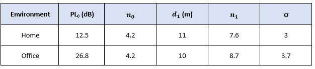
Most of these measurements for the NIST PAP02 Task 6 channel model were taken with transmitters and receivers located in hallways with distances ranging from 5 m to 45 m.
Transmit Power
Transmit power is the power of the radio frequency signal generated by the transmitter. Increasing the transmit power increases the likelihood that the signal can be transmitted over longer distances. Bluetooth supports transmit power from -20 dBm (0.01 mW) to 20 dBm (100 mW).
Antenna Gain
Antenna gain is the factor by which the antenna improves the total radiated power. Bluetooth designers can choose to implement a variety of antenna options. Bluetooth devices typically achieve an antenna gain in the range from -10 dBi to 10 dBi.
End-to-End Bluetooth LE Simulation Procedure
The end-to-end Bluetooth LE PHY simulations estimate the BER and the distance between the transmitter and receiver by considering a specific environment with RF impairments and AWGN added to the transmission packets.
For a given set of simulation parameters, obtain the signal-to-noise ratio (SNR) at the receiver by assuming a fixed noise figure. For the obtained value of SNR including the path loss, generate the Bluetooth LE waveform using bleWaveformGenerator function. Distort the generated waveform with RF impairments and AWGN. Each packet is distorted by these RF impairments:
DC offset
Carrier frequency offset
Carrier phase offset
Timing drift
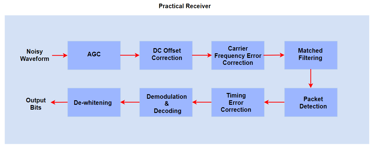
The noisy packets are processed through a practical Bluetooth LE receiver that performs these operations:
Automatic gain control (AGC)
DC removal
Carrier frequency offset correction
Matched filtering
Packet detection
Timing error detection
Demodulation and decoding
De-whitening
The end-to-end example chain is summarized in these block diagrams
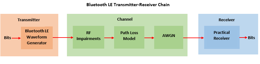
The BER is obtained by comparing the transmitted and recovered data bits.
Configure Simulation Parameters
In this example, the distance between the transmitter and receiver is estimated based on the environment and the power levels of the signal at the transmitter and receiver. Configure the parameters using the bluetoothRangeConfig object.
Configure parameters related to the communication link between the transmitter and receiver
rangeConfig = bluetoothRangeConfig; rangeConfig.Environment ="Outdoor"; % Environment rangeConfig.Mode =
'LE1M'; % PHY transmission mode rangeConfig.ReceiverSensitivity =
-73 ; % Receiver sensitivity in dBm rangeConfig.TransmitterPower =
0; % Transmit power in dBm rangeConfig.TransmitterAntennaGain =
0; % Transmitter antenna gain in dB rangeConfig.ReceiverAntennaGain =
0; % Receiver antenna gain in dB if strcmp(rangeConfig.Environment,'Industrial') % Link margin(dB) assumed in the simulation rangeConfig.LinkMargin = 7 elseif strcmp(rangeConfig.Environment,'Outdoor') rangeConfig.LinkMargin = 15 else rangeConfig.LinkMargin = 0 end
rangeConfig =
  bluetoothRangeConfig with properties:

                 Environment: 'Outdoor'
             SignalPowerType: 'ReceiverSensitivity'
                        Mode: 'LE1M'
         ReceiverSensitivity: -73
                  LinkMargin: 15
            TransmitterPower: 0
      TransmitterAntennaGain: 0
         ReceiverAntennaGain: 0
        TransmitterCableLoss: 1.2500
           ReceiverCableLoss: 1.2500
    TransmitterAntennaHeight: 1
       ReceiverAntennaHeight: 1

   Read-only properties:
                FSPLDistance: 5.8256
               PathLossModel: 'TwoRayGroundReflection'
Configure parameters for waveform generation
sps = 8; % Samples per symbol dataLen =254; % Data length in bytes channelIndex =
37; % Random channel index
Configure RF impairments
frequencyOffset =5800; % Frequency offset in Hz phaseOffset =
5; % Phase offset in degrees initoff = 0.15*sps; % Static timing offset stepsize = 20*1e-6; % Timing drift in ppm, Max range is +/- 50 ppm dcOffset = 20; % Percentage related to maximum amplitude value
Generate Bluetooth LE Waveform
Generate Bluetooth LE waveform based on waveform configuration parameters.
% Default access address for periodic advertising channels
accessAddress = [0 1 1 0 1 0 1 1 0 1 1 1 1 1 0 1 1 0 0 1 0 0 0 1 0 1 1 1 0 0 0 1]';

% Random data bits generation
txBits = randi([0 1],dataLen*8,1,'int8');

% Generate Bluetooth LE waveform
txWaveform = bleWaveformGenerator(txBits,'Mode',rangeConfig.Mode,...
    'SamplesPerSymbol',sps,...
    'ChannelIndex',channelIndex,...
    'AccessAddress',accessAddress);
Configure noise and signal power at the receiver
The noise floor of the receiver is simulated with thermal noise. The height of the noise floor determines the SNR at the receiver. The noise figure of the receiver determines the level of noise floor.
NF = 6;                                            % Noise figure (dB)
T = 290;                                           % Ambient temperature (K)
dBm2dBFactor = 30;                                 % Factor for converting dBm to dB

% Symbol rate based on the PHY transmission mode
symbolRate = 1e6;
if strcmp(rangeConfig.Mode,'LE2M')
    symbolRate = 2e6;
end
BW = sps*symbolRate; % Bandwidth (Hz)
k = 1.3806e-23;                   % Boltzmann constant (J/K)
noiseFloor = 10*log10(k*T*BW)+NF; % Nosie floor in dB

% Measure the path loss and signal power at the receiver.
[pldB,sigPowerdBm] = pathLoss(rangeConfig);
measuredPowerVector = sigPowerdBm - dBm2dBFactor;
snrdB = measuredPowerVector - noiseFloor; % SNR in dB
plLinear = 10^(pldB/20); % Convert path loss from dB to linear scale
Distort Bluetooth LE Waveform
Distort the generated Bluetooth LE waveform using RF impairments, path loss, and AWGN.
Add RF Impairments
The RF impairments are generated randomly and added to the Bluetooth LE waveform.
% Create and configure the System objects for impairments
initImp = helperBLEImpairmentsInit(rangeConfig.Mode,sps);

% Configure RF impairments
initImp.pfo.FrequencyOffset = frequencyOffset;               % Frequency offset in Hz
initImp.pfo.PhaseOffset = phaseOffset;                       % Phase offset in degrees
initImp.vdelay = (initoff:stepsize:initoff+stepsize*(length(txWaveform)-1))';
initImp.dc = dcOffset;

% Pass generated Bluetooth LE waveform through RF impairments
txImpairedWfm = helperBLEImpairmentsAddition(txWaveform,initImp);
Attenuate Impaired Bluetooth LE Waveform
Attenuate the impaired Bluetooth LE waveform.
% Attenuate Bluetooth LE waveform
attenWaveform  = txImpairedWfm.*10^(measuredPowerVector/20);
Add AWGN
Add AWGN to the attenuated Bluetooth LE waveform.
rxWaveform = awgn(attenWaveform,snrdB,'measured');Simulation Results
Estimate and display the BER and the distance between the transmitter and the receiver by processing the distorted Bluetooth LE waveform through the practical receiver.
Receiver Processing
To retrieve the data bits, pass the attenuated, AWGN-distorted Bluetooth LE waveform through the practical receiver.
% Configure the receiver parameters in a structure
rxCfg = struct(Mode=rangeConfig.Mode,SamplesPerSymbol=sps,ChannelIndex=channelIndex,...
    DFPacketType='Disabled',AccessAddress=accessAddress);
rxCfg.CoarseFreqCompensator = comm.CoarseFrequencyCompensator(Modulation="OQPSK",...
    SampleRate=BW,...
    SamplesPerSymbol=2*sps,...
    FrequencyResolution=100);
rxCfg.PreambleDetector = comm.PreambleDetector(Detections="First");

% Recover data bits using practical receiver
[rxBits,accessAddress] = helperBLEPracticalReceiver(rxWaveform,rxCfg);
Estimate BER
Estimate value of the BER based on the retrieved and the transmitted data bits.
% Obtain BER by comparing the transmitted and recovered bits
if(length(txBits) == length(rxBits))
    ber = (sum(xor(txBits,rxBits))/length(txBits));
else
    disp('Unable to compute BER due to length mismatch in input and decoded bits')
end
Estimate Distance
Estimate the distance between the transmitter and the receiver.
% Estimate the distance between the transmitter and the receiver based on
% the environment
distance = bluetoothRange(rangeConfig);
Display Results
Display the estimated results and plot the spectrum of the transmitted and received Bluetooth LE waveform.
% Display estimated BER and distance between the transmitter and the
% receiver.
disp(['Input configuration: ', newline , '    PHY transmission mode: ', rangeConfig.Mode,....
    newline,'    Environment: ', rangeConfig.Environment]);
Input configuration:
    PHY transmission mode: LE1M
    Environment: Outdoor
disp(['Estimated outputs: ', newline , '    Path loss : ', num2str(pldB), ' dB'....
    newline,'    Distance between the transmitter and receiver: ', num2str(round(distance(1))), ' to ', num2str(round(distance(2))), ' m', newline, ...
    '    Free space path loss distance: ', num2str(round(rangeConfig.FSPLDistance)), ' m', newline, '    BER: ', num2str(ber)]);
Estimated outputs:
    Path loss : 55.5 dB
    Distance between the transmitter and receiver: 5 to 8 m
    Free space path loss distance: 6 m
    BER: 0
% Plot the spectrum of the transmitted and received Bluetooth LE waveform
specAnalyzer = spectrumAnalyzer('SampleRate',symbolRate*sps, ...
    'Title','Spectrum of Transmitted and Received Bluetooth LE Signals', ...
    'ShowLegend',true, ...
    'ChannelNames',{'Transmitted Bluetooth LE signal','Received Bluetooth LE signal'});

specAnalyzer(txWaveform,rxWaveform);
release(specAnalyzer);
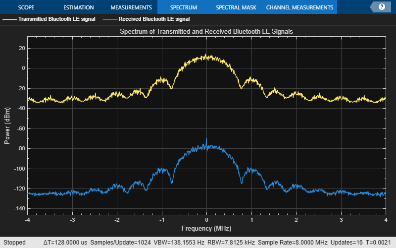
This example demonstrates an end-to-end Bluetooth LE simulation for different PHY transmission modes by considering the path loss model, RF impairments, and AWGN. The obtained simulation results display the path loss, estimated distance between the transmitter and receiver, and BER. The spectrum of the transmitted and received Bluetooth LE waveform is visualized by using a spectrum analyzer.
Appendix
The example uses these helper functions:
helperBLEImpairmentsAddition— Add RF impairments to the Bluetooth LE waveformhelperBLEPracticalReceiver— Demodulate and decodes the received Bluetooth LE waveformhelperBLEImpairmentsInit— Initialize RF impairment parameters
Selected Bibliography
[1] Bluetooth Special Interest Group (SIG). "Bluetooth Core Specification". Version 5.3. https://www.bluetooth.com.
[2] Path Loss Models Used in Bluetooth Range Estimator. Bluetooth Special Interest Group (SIG). https://www.bluetooth.com.
[3] Rappaport, Theodore. Wireless Communication – Principles and Practice. Prentice Hall, 1996.
[4] NIST Smart Grid Interoperability Panel Priority Action Plan 2: Guidelines for Assessing Wireless Standards for Smart Grid Applications. National Institute of Standards and Technology, U.S. Department of Commerce, 2014.