Bluetooth BR/EDR Power and Spectrum Tests
This example shows how to perform radio frequency (RF) physical layer (PHY) transmitter tests specific to power and spectrum on Bluetooth® basic rate (BR) and enhanced data rate (EDR) transmitted waveform by using Bluetooth® Toolbox features. The example also verifies whether these test measurement values are within the limits specified by the Bluetooth RF-PHY Test Specifications [1].
Objectives of Bluetooth RF-PHY tests
The Bluetooth RF-PHY Test Specifications [1] defined by the Bluetooth Special Interest Group (SIG) includes RF-PHY tests for transmitters and receivers. The objectives of these RF-PHY tests are to:
Ensure interoperability between all Bluetooth devices.
Verify that a basic level of system performance is guaranteed for all Bluetooth products.
Each test case has a specific test procedure and an expected outcome, which must be met by the implementation under test (IUT).
Power and Spectrum Tests
This example shows how to perform power and spectrum test measurements on Bluetooth BR/EDR transmitted waveform according to the Bluetooth RF-PHY Test Specifications [1].
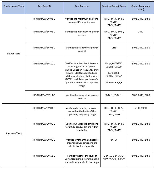
Power Tests: These tests verify whether the peak power, average power, power density, and power control of the transmitted Bluetooth signals are within the limits specified in the Bluetooth RF-PHY Test Specifications [1]. For more information about these tests, see sections 4.5.1, 4.5.2, 4.5.3, 4.5.10, and 4.5.14 of the Bluetooth RF-PHY Test Specifications.
Spectrum Tests: These tests verify whether the signal emissions are within the operating frequency range specified in the Bluetooth RF-PHY Test Specifications. For more information about these tests, see sections 4.5.4, 4.5.5, 4.5.6, and 4.5.13 of the Bluetooth RF-PHY Test Specifications.
This table shows various RF-PHY transmitter tests this example implements.
Configure Simulation Parameters
Specify the test case ID, center frequency, packet type, samples per symbol, and output power.
% Select test case ID to perform power and spectrum tests testCaseID ='RF/TRM/CA/BV-01-C'; % Select the frequency of operation for the IUT as shown in this table % ---------------------------- % | Operating | Frequency in | % | Frequency | MHz | % ---------------------------- % | Low | 2402 | % | Mid | 2440 | % | High | 2480 | % ---------------------------- % Specify the type of center frequency required to perform the test case % ----------------------------------------------------- % | Test Case ID | Type of Center Frequency | % ----------------------------------------------------- % | | | % | RF/TRM/CA/BV-01-C | 'Low','Mid','High' | % | | | % | | | % | RF/TRM/CA/BV-02-C | 'Mid' | % | | | % | | | % | RF/TRM/CA/BV-03-C | 'Low','Mid','High' | % | | | % | | | % | RF/TRM/CA/BV-04-C | 'Low','High' | % | | | % | | | % | RF/TRM/CA/BV-05-C | 'Low','Mid','High' | % | | | % | | | % | RF/TRM/CA/BV-06-C | 'Low','Mid','High' | % | | | % | | | % | RF/TRM/CA/BV-10-C | 'Low','Mid','High' | % | | | % | | | % | RF/TRM/CA/BV-13-C | 'Low','Mid','High' | % | | | % | | | % | RF/TRM/CA/BV-14-C | 'Low','Mid','High' | % | | | % | | | % ----------------------------------------------------- centerFrequency =
'Low'; % Specify the type of packet required to perform the test case packetType = 'DH1'; sps = 8; % Number of samples per symbol outputPower =
20; % Output power in dBm (must be in the range [-20,20]) stepSize =
2; % Step size in dB (for power control tests % {'RF/TRM/CA/BV-03-C', % 'RF/TRM/CA/BV-14-C'})
Configure Test Parameters and Generate Bluetooth Test Waveform
Configure the test parameters and generate the Bluetooth test waveform by using the helperBluetoothPowerTestConfig helper function.
% Get test parameters and test waveform
[configParams,txWaveformBaseBand] = helperBluetoothPowerTestConfig(testCaseID,centerFrequency,packetType,sps,outputPower,stepSize);
configParams.numDominantFreq = 6;

% Interpolation factor for upconversion
interpFactor = ceil(2*configParams.StopFreq/configParams.SampleRate);

% Create a digital upconverter System object
upConv = dsp.DigitalUpConverter(InterpolationFactor=interpFactor, ...
    SampleRate=configParams.SampleRate, ...
    Bandwidth=1e6, ...
    CenterFrequency=configParams.CenterFreq, ...
    StopbandAttenuation=120);

% Upconvert the baseband waveform to passband and scale the waveform to
% required power
dBmConvFactor = 30;
scalingFactor = 10^((outputPower - dBmConvFactor)/20);
txWaveform = scalingFactor*upConv(txWaveformBaseBand);
Perform Spectrum Analysis on the Waveform
Perform the spectrum analysis by using the helperBluetoothPowerTestAnalysis helper function. The function returns the output power along with the frequency, time, or step size data from the spectrum.
[outPower,testMeas] = helperBluetoothPowerTestAnalysis(testCaseID,configParams,txWaveform,interpFactor);
Calculate Test Measurements
Calculate the test measurements for each test based on the spectrum analysis outputs by using the helperBluetoothPowerTestMeasurements helper function.
output = helperBluetoothPowerTestMeasurements(testCaseID,centerFrequency,outPower,testMeas);
Simulation Results
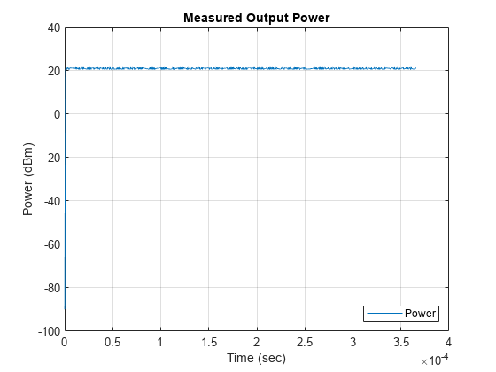
Validate the test results and display the verdict by using the helperBluetoothPowerTestVerdict helper function.
helperBluetoothPowerTestVerdict(testCaseID,output);
Measured average power - 21.110625 dBm
Measured peak power - 21.598563 dBm
Verdict - Output power test passed
This example demonstrates the Bluetooth BR/EDR RF-PHY transmitter test measurements specific to power and spectrum. The simulation results verify that the computed test measurement values are within the limits specified by the Bluetooth RF-PHY Test Specifications [1].
Appendix
The example uses these helpers:
helperBluetoothPowerTestConfig— Configure test parameters and generate Bluetooth test waveformhelperBluetoothPowerTestAnalysis— Perform analysis of Bluetooth test waveforms in time and frequency domainhelperBluetoothPowerTestMeasurements— Calculate test measurementshelperBluetoothPowerTestVerdict— Validate test results and displays the verdict
Selected Bibliography
Bluetooth Special Interest Group (SIG). “Bluetooth RF-PHY Test Specifications”, v1.2/2.0/2.0, EDR/2.1/2.1, EDR/3.0/3.0, HS (), RF.TS/3.0.H.1, Section 4.5. 2009. https://www.bluetooth.com.
Bluetooth Special Interest Group (SIG). "Core System Package [BR/EDR Controller Volume]". Bluetooth Core Specification. Version 5.3, Volume 2. https://www.bluetooth.com.