Bluetooth LE Output Power and In-Band Emissions Tests
This example shows how to perform radio frequency (RF) physical layer (PHY) transmitter tests specific to output power and in-band emissions on Bluetooth® low energy (LE) transmitted waveforms by using Bluetooth® Toolbox features. This example also verifies whether these test measurement values are within the limits specified by the Bluetooth RF-PHY Test Specifications [ 3 ].
Objectives of Bluetooth LE RF-PHY tests
The Bluetooth RF-PHY Test Specifications [ 3 ] defined by Bluetooth Special Interest Group (SIG) includes RF-PHY tests for both transmitter and receiver. The objectives of these RF-PHY tests are to:
Ensure interoperability between all Bluetooth devices.
Ensure a basic level of system performance for all Bluetooth products.
Each test case has a specified test procedure and an expected outcome, which must be met by the implementation under test (IUT).
RF-PHY Transmitter Tests
This example performs output power and in-band emissions test measurements according to the Bluetooth RF-PHY Test Specifications [ 3 ]. The output power measurement is designed to ensure that power levels are high enough to maintain interoperability with other Bluetooth devices and low enough to minimize interference within the ISM band. The in-band emission test is to verify that the level of unwanted signals within the frequency range from the transmitter do not exceed the specified limits. The test case IDs corresponding to the tests considered in this example are as follows:
Output Power:
RF-PHY/TRM/BV-01-C: This test verifies the maximum peak and average power emitted from the IUT are within limits.
RF-PHY/TRM/BV-15-C: This test verifies the maximum peak and average power emitted from the IUT are within limits, when transmitting with a constant tone extension (CTE).
In-band Emissions:
RF-PHY/TRM/BV-03-C: This test verifies that the in-band emissions are within limits when the transmitter is operating with uncoded data at 1 Ms/s.
RF-PHY/TRM/BV-08-C: This test verifies that the in-band emissions are within limits when the transmitter is operating with uncoded data at 2 Ms/s.
Configure the Test Parameters
You can change phyMode, packetType, Fc, outputPower and numDominantFreq parameters based on the PHY transmission mode, packet type, frequency of operation, output power and number of dominant frequencies, respectively.
% Select PHY transmission mode {'LE1M','LE2M'} according to the Bluetooth RF-PHY Test % Specifications phyMode ="LE1M"; % Select packet type {'Disabled','ConnectionCTE'} for transmitting the % packet with or without CTE. The CTE information field position is same % for LE test packet and data packet. For CTE-based RF-PHY tests, set the % packet type to 'ConnectionCTE'. packetType =
"Disabled"; % Select frequency of operation for IUT based on the generic access profile % (GAP) role(s) as shown in the table below. % -------------------------------------------------------------------------------- % | Operating | Peripheral & Central Devices | Broadcaster & Observer Devices | % | Frequency | | | % | (MHz) |----------------------------------|---------------------------------| % | | Output Power | In-band Emissions | Output Power | In-band Emissions| % | | Test | Test | Test | Test | % |-----------|--------------|-------------------|--------------|------------------| % | Lowest | 2402 | 2406 | 2402 | 2402 | % | Middle | 2440 | 2440 | 2426 | 2440 | % | Highest | 2480 | 2476 | 2480 | 2480 | % -------------------------------------------------------------------------------- Fc = 2440e6; % Frequency of operation in Hz payloadLength =
37; % Payload length in bytes, must be in the range [37,255] sps = 32; % Number of samples per symbol, minimum of 32 sps as per the test specifications outputPower =
20; % Output power in dBm, must be in the range [-20,20] pulseLength =
2; % Length of the frequency pulse shape in the range [1,4] modulationIndex =
0.5; % Modulation index of GFSK in the range [0.45,0.55]
Select number of dominant frequencies for in-band emissions test, must be in the range [1,78] and [1,74] for LE1M and LE2M modes, respectively.
numDominantFreq =  6;
6;The number of dominant frequencies represents the number of test frequencies near the operating frequency at which the in-band emissions test is to be performed. The number chosen in this example leads to a short simulation. For performing complete in-band emissions test, change the numDominantFreq parameter to maximum number of dominant frequencies as specified in the Section 4.4.1 of the Bluetooth RF-PHY Test Specifications [ 3 ].
Generate Bluetooth LE Test Waveforms
Generate Bluetooth LE test waveform using bluetoothTestWaveform function and bluetoothTestWaveformConfig object.
testConfig = bluetoothTestWaveformConfig;
testConfig.PayloadType = 0; % Payload type for PRBS9 sequence
testConfig.PayloadLength = payloadLength;
testConfig.SamplesPerSymbol = sps;
testConfig.Mode = phyMode;
testConfig.PacketType = packetType;
testConfig.PulseLength = pulseLength;
testConfig.ModulationIndex = modulationIndex;
% testConfig.PulseLength = 2;
if strcmp(packetType,'ConnectionCTE')
    % Length of CTE in 8 microseconds units
    testConfig.CTELength = 2; % Must be in the range [2, 20]
    % Type of CTE
    testConfig.CTEType = [0;0]; % [0;0] for Angle of Arrival CTE
end
waveform = bluetoothTestWaveform(testConfig);

% Calculate sampling rate in Hz based on PHY transmission mode
Rsym = 1e6;
if strcmp(phyMode,'LE2M')
    Rsym = 2e6;
end
Fs = Rsym*sps;

% Apply frequency upconversion to obtain a passband signal for the
% specified frequency of operation.
maxFreq = 2485e6; % in Hz
interpFactor = ceil(2*maxFreq/Fs); % Interpolation factor for upconversion to
                                   % cover Bluetooth LE RF frequency band (2400e6 to 2485e6)

% Change the stopband frequency in Hz based on the PHY transmission mode
stopbandFreq = 2e6;
if strcmp(phyMode,'LE2M')
    stopbandFreq = 4e6;
end

% Create a digital upconverter System object
upConv = dsp.DigitalUpConverter(...
              'InterpolationFactor', interpFactor,...
              'SampleRate', Fs,...
              'Bandwidth', 2e6,...
              'StopbandAttenuation', 44,...
              'PassbandRipple',0.5,...
              'CenterFrequency',Fc,...
              'StopbandFrequencySource','Property',...
              'StopbandFrequency', stopbandFreq);

% Upconvert the baseband waveform to passband
dBdBmConvFactor = 30;
scalingFactor = 10^((outputPower-dBdBmConvFactor)/20);
upConvWaveform = scalingFactor*upConv(waveform);
Perform Output Power Test
rbwOutputPower = 3e6; % Resolution bandwidth, in HzTo perform power measurement in the time domain, frequency span must be set to 0. Span 0 can be replicated by taking power values from the spectrogram at frequency of operation (Fc). Frequency limits are considered starting from frequency of operation (Fc) up to maximum frequency in the frequency band.
[P,F,T] = pspectrum(upConvWaveform,interpFactor*Fs,'spectrogram',...
                               'TimeResolution',1/rbwOutputPower,...
                               'FrequencyLimits',[Fc,maxFreq]);
powerAtFc = P(1,:); % Extract power values at Fc (F(1) = Fc)

% Calculate average power, AVGPOWER over at least 20% to 80% of the
% duration of the burst as specified in Section 4.4.1 of the Bluetooth
% RF-PHY Test Specifications [3].
powerAvgStartIdx = floor(0.2*length(powerAtFc));
powerAvgStopIdx = floor(0.8*length(powerAtFc));
avgPower = round(10*log10(mean(powerAtFc(powerAvgStartIdx:powerAvgStopIdx)))+dBdBmConvFactor);

% Calculate peak power, PEAKPOWER
peakPower = 10*log10(max(powerAtFc))+dBdBmConvFactor;

% Plot power vs time
powerAtFcdBm = 10*log10(powerAtFc) + dBdBmConvFactor;
figure,plot(T,powerAtFcdBm)
grid on;
xlabel('Time (sec)');
ylabel('Power (dBm)');
title('Measured Output Power');
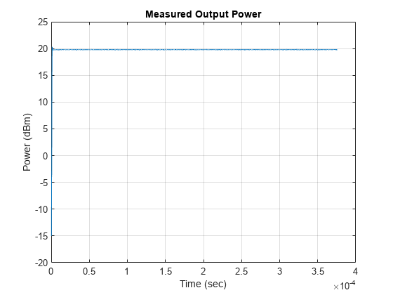
% Pass verdict - All measured values shall fulfill the following conditions:
%
% * Peak power <= (Average power + 3 dB)
% * -20dBm <= Average power <= 20dBm
%
fprintf('Measured average power and peak power are %f dBm and %f dBm, respectively.\n',avgPower,peakPower);
Measured average power and peak power are 20.000000 dBm and 20.301629 dBm, respectively.
if avgPower <= 20 && avgPower >= -20 && (peakPower <= (avgPower+3))
    fprintf('Output power test passed.\n');
else
    fprintf('Output power test failed.\n');
end
Output power test passed.
Perform In-band Emissions Test
if strcmp(packetType,'Disabled')
    % The function, <matlab:edit('helperBLEInbandEmissionsParams.m')
    % helperBLEInbandEmissionsParams.m>, is configured to generate dominant
    % test frequency parameters.
    [testFreq,idx1,idx2] = helperBLEInbandEmissionsParams(Fc,numDominantFreq,phyMode);

    % For each test frequency measure the power levels at the following 10
    % frequencies.
    numOffsets = 10;
    freqOffset = -450e3+(0:numOffsets-1)*100e3;
    adjChannelFreqOffsets = (freqOffset+testFreq-Fc).';
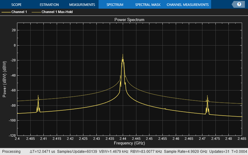
Create a spectrum analyzer to visualize the upconverted waveform.
    spec = spectrumAnalyzer('SampleRate',Fs*interpFactor,...
        'YLimits', [-120 30], ...
        'Title', 'Power Spectrum',...
        'YLabel', 'Power (dBW)',...
        'SpectrumUnits','dBW',...
        'ShowLegend',true,...
        'FrequencySpan','Start and stop frequencies',...
        'StartFrequency',2400e6,...
        'StopFrequency',maxFreq,...
        'PlotMaxHoldTrace',true,...
        'PlotAsTwoSidedSpectrum',false);
    spec(upConvWaveform);
Create an ACPR System object™ to calculate adjacent channel power as specified in the Section 4.4.1 of the Bluetooth RF-PHY Test Specifications [3].
    rbw = 100e3;                                           % Resolution bandwidth, in Hz
    acprMeas = comm.ACPR('SampleRate',Fs*interpFactor,...
        'MainChannelFrequency',Fc,...
        'MainMeasurementBandwidth',2e6,...
        'AdjacentMeasurementBandwidth',1e5,...
        'PowerUnits','dBW',...
        'MainChannelPowerOutputPort',true,...
        'AdjacentChannelPowerOutputPort',true, ...
        'MaxHold',true, ...
        'SpectralEstimation',"Specify window parameters",...
        'Window','Hann', ...
        'SegmentLength',Fs*interpFactor/rbw);
Measure adjacent channel power across the test frequencies.
    adjChnlPwr = zeros(numOffsets,numDominantFreq);
    for nFreq = 1:numDominantFreq
        % Assign the 10 frequency offsets at each test frequency to Adjacent channel offsets
        acprMeas.AdjacentChannelOffset = adjChannelFreqOffsets(:,nFreq)';

        % Compute adjacent channel power in dBW
        [~,mainChnlPwr,adjChnlPwr(:,nFreq)] = acprMeas(upConvWaveform);
        release(acprMeas)
    end

    % Power levels at 10 frequency offsets at each test frequency are
    % calculated by adding main channel power to ACPR.
    adjChannelPower = adjChnlPwr(:,1:numDominantFreq);

    % Compute the power at each test frequency by adding all the powers
    % measured at 10 frequency offsets.
    adjPowerAtTestFreq = 10*log10(sum(10.^(adjChannelPower(:,1:numDominantFreq)/10))) + dBdBmConvFactor;
Visualize the results and verdicts of the test.
    % Plot the adjacent channel powers
    tick = 1:numel(adjPowerAtTestFreq);
    ticklabel = testFreq/1e9;
    figure;
    bar(adjPowerAtTestFreq, 'BaseValue', -120, 'FaceColor', 'yellow');
    set(gca, 'XTick', tick, 'XTickLabel', ticklabel, 'YLim', [-120 -20]);
    for i = tick
        text(i, adjPowerAtTestFreq(i), sprintf('%0.2f',adjPowerAtTestFreq(i)), ...
            'HorizontalAlignment', 'Center', 'VerticalAlignment', 'Top');
    end
    title('In-Band Emission Test Measurement');
    xlabel('Frequency (GHz)');
    ylabel('Power (dBm)');

    % Pass verdict- All measured values shall fulfill the following conditions:
    % For LE1M PHY transmission mode
    %
    % * powerAtTestFreq <= -20 dBm for testFreq = Fc ± 2 MHz
    % * powerAtTestFreq <= -30 dBm for testFreq = Fc ± [3+n] MHz; where
    %   n=0,1,2,...
    %
    % For LE2M PHY transmission mode
    %
    % * powerAtTestFreq <= -20 dBm for testFreq = Fc ± 4 MHz AND testFreq = Fc
    % ± 5 MHz
    % * powerAtTestFreq <= -30 dBm for testFreq = Fc ± [6+n] MHz; where
    %   n=0,1,2,...
    %
    for i = 1:numDominantFreq
        fprintf('Measured power at test frequency (Fc%+de6) is %.3f dBm.\n',(Fc-testFreq(i))*1e-6,adjPowerAtTestFreq(i));
    end
    if (all(adjPowerAtTestFreq(idx1) <= -20)||isempty(idx)) && (all(adjPowerAtTestFreq(idx2) <= -30)||isempty(idx2))
        fprintf('In-band emissions test passed.\n');
    else
        fprintf('In-band emissions test failed.\n');
    end
end
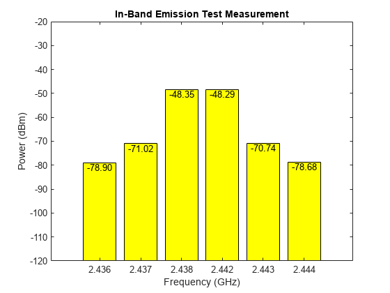
Measured power at test frequency (Fc+4e6) is -78.903 dBm.
Measured power at test frequency (Fc+3e6) is -71.017 dBm.
Measured power at test frequency (Fc+2e6) is -48.346 dBm.
Measured power at test frequency (Fc-2e6) is -48.286 dBm.
Measured power at test frequency (Fc-3e6) is -70.743 dBm.
Measured power at test frequency (Fc-4e6) is -78.683 dBm.
In-band emissions test passed.
This example demonstrated the transmitter test measurements specific to output power and in-band emissions on Bluetooth LE transmitted waveforms as per the Bluetooth RF-PHY Test Specifications [ 3 ].
Appendix
This example uses this helper function:
helperBLEInbandEmissionsParams.m: Generate test frequency(s) for in-band emissions test
Selected Bibliography
Bluetooth Technology Website. “Bluetooth Technology Website | The Official Website of Bluetooth Technology.” Accessed November 22, 2021. https://www.bluetooth.com.
Bluetooth Special Interest Group (SIG). "Core System Package [Low Energy Controller Volume]". Bluetooth Core Specification. Version 5.3, Volume 6. https://www.bluetooth.com.
Bluetooth RF-PHY Test Specification, Section 4.4.1.