comm.EyeDiagram
(Removed) Display eye diagram of time-domain signals
comm.EyeDiagram has been removed. To display the eye diagram of a signal, use the eyediagram
function instead. For more details on the recommended workflow, see
Version History.
Description
The comm.EyeDiagram
System object™ displays multiple traces of a modulated signal to produce an eye diagram. You
can use the object to reveal the modulation characteristics of the signal, such as the effects
of pulse shaping or channel distortions. The eye diagram can measure signal characteristics
and plot horizontal and vertical bathtub curves when the jitter and noise comply with the
dual-Dirac model [1].
To display the eye diagram of an input signal:
Create the
comm.EyeDiagram
object and set its properties.Call the object with arguments, as if it were a function.
To learn more about how System objects work, see What Are System Objects?
Creation
Description
creates an eye diagram
System object with default property values. ed
= comm.EyeDiagram
sets properties using one or more name-value pair argument. Enclose each property name in
single quotes. Unspecified properties have default values.ed
= comm.EyeDiagram(Name
,Value
)
Example: comm.EyeDiagram('SampleRate',2,'DisplayMode','2D color
histogram')
Properties
Unless otherwise indicated, properties are nontunable, which means you cannot change their
values after calling the object. Objects lock when you call them, and the
release
function unlocks them.
If a property is tunable, you can change its value at any time.
For more information on changing property values, see System Design in MATLAB Using System Objects.
Name
— Title of eye diagram window
'Eye Diagram'
(default) | character vector
Title of eye diagram window, specified as a character vector.
Tunable: Yes
Data Types: char
SampleRate
— Sample rate of input signal
1
(default) | positive real-valued scalar
Sample rate of the input signal in hertz, specified as a positive real-valued scalar.
Data Types: double
SamplesPerSymbol
— Number of samples per symbol
8
(default) | positive integer
Number of samples per symbol, specified as a positive integer.
Tunable: Yes
Data Types: double
SampleOffset
— Number of samples to skip before plotting the first point
0
(default) | nonnegative integer
Number of samples to skip before plotting the first point, specified as a nonnegative integer. To avoid irregular behavior, specify the offset to be less than the product of the SamplesPerSymbol and SymbolsPerTrace properties.
Tunable: Yes
Data Types: double
SymbolsPerTrace
— Number of symbols per trace
2
(default) | positive integer
Number of symbols per trace, specified as a positive integer. To obtain eye
measurements and visualize bathtub curves, use the default value of
2
.
Tunable: Yes
Data Types: double
TracesToDisplay
— Number of traces to display
40
(default) | positive integer
Number of traces to display, specified as a positive integer.
Tunable: Yes
Dependencies
To enable this property, set DisplayMode property to
'Line plot'
.
Data Types: double
DisplayMode
— Eye diagram display mode
'Line plot'
(default) | '2D color histogram'
Eye diagram display mode, specified as one of these values.
'Line plot'
— Overlay traces by plotting one line for each of the last TracesToDisplay traces.'2D color histogram'
— Display a color gradient that shows how often the input matches different time and amplitude values.
Tunable: Yes
Data Types: char
EnableMeasurements
— Option to enable eye diagram measurements
false
(default) | true
Option to enable eye diagram measurements, specified as true
or
false
. Set this property to true
to display the
measurement pane and calculations in the eye diagram.
Tunable: Yes
Data Types: logical
ShowBathtub
— Option to enable visualization of bathtub curves
'None'
(default) | 'Horizontal'
| 'Vertical'
| 'Both'
Option to enable visualization of bathtub curves, specified as
'None'
, 'Horizontal'
,
'Vertical'
, or 'Both'
.
Tunable: Yes
Dependencies
To enable this property, set the EnableMeasurements
property to true
.
Data Types: char
OverlayHistogram
— Histogram overlay
'None'
(default) | 'Jitter'
| 'Noise'
Histogram overlay, specified as 'None'
,
'Jitter'
, or 'Noise'
.
To overlay a horizontal histogram on the eye diagram, set this property to
'Jitter'
.To overlay a vertical histogram on the eye diagram, set this property to
'Noise'
.To display no histogram overlay, set this property to
'None'
.
Tunable: Yes
Dependencies
To enable this property, set the DisplayMode property to
'2D color histogram'
and EnableMeasurements
property to true
.
Data Types: char
DecisionBoundary
— Amplitude level threshold
0
(default) | real-valued scalar
Amplitude level threshold in volts, specified as a real-valued scalar. This property separates the different signaling regions for horizontal (jitter) histograms. Jitter histograms reset when this property changes.
For non-return-to-zero (NRZ) signals, set DecisionBoundary
to
0. For return-to-zero (RZ) signals, set DecisionBoundary
to half
the maximum amplitude.
Tunable: Yes
Dependencies
To enable this property, set the EnableMeasurements
property to true
.
Data Types: double
EyeLevelBoundaries
— Time range for calculating eye levels
[40 60]
(default) | two-element row vector
Time range for calculating eye levels, specified as a two-element row vector. Specify the vector values as percentages of the symbol duration.
Tunable: Yes
Dependencies
To enable this property, set the EnableMeasurements
property to true
.
Data Types: double
RiseFallThresholds
— Amplitude levels of the rise and fall transitions
[10 90]
(default) | two-element row vector
Amplitude levels of the rise and fall transitions, specified as a two-element row vector. Specify the vector values as percentages of the eye amplitude. The crossing histograms of the rise and fall thresholds reset when this property changes.
Tunable: Yes
Dependencies
To enable this property, set the EnableMeasurements
property to true
.
Data Types: double
Hysteresis
— Amplitude tolerance of the horizontal crossings
0
(default) | real-valued scalar
Amplitude tolerance of the horizontal crossings in volts, specified as a real-valued scalar. Increase this value to provide more tolerance to spurious crossings due to noise. Jitter and the rise and fall histograms reset when this property changes.
Tunable: Yes
Dependencies
To enable this property, set the EnableMeasurements
property to true
.
Data Types: double
BERThreshold
— BER used for eye measurements
1e-12
(default) | scalar in the range [0, 0.5]
Bit error rate (BER) used for eye measurements, specified as a scalar in the range [0, 0.5]. The System object uses this value to measure the random jitter, the total jitter, horizontal eye openings, and vertical eye openings.
Tunable: Yes
Dependencies
To enable this property, set the EnableMeasurements
property to true
.
Data Types: double
BathtubBER
— BER values used to calculate openings of bathtub curves
[0.5 10.^-(1:12)]
(default) | vector
BER values used to calculate the openings of bathtub curves, specified as a vector of elements in the range [0, 0.5]. Horizontal and vertical eye openings are calculated for each of the values specified by this property.
Tunable: Yes
Dependencies
To enable this property, set the EnableMeasurements
property to true
and ShowBathtub property to
'Both'
, 'Horizontal'
, or
'Vertical'
.
Data Types: double
MeasurementDelay
— Duration of initial data discarded from measurements
0
(default) | nonnegative scalar
Duration of initial data discarded from measurements in seconds, specified as a nonnegative scalar.
Dependencies
To enable this property, set the EnableMeasurements
property to true
.
Data Types: double
OversamplingMethod
— Oversampling method
'None'
(default) | 'Input interpolation'
| 'Histogram interpolation'
Oversampling method, specified as 'None'
, 'Input
interpolation'
, or 'Histogram interpolation'
.
To plot eye diagrams as quickly as possible, set
OversamplingMethod
to 'None'
. The drawback to
not oversampling is that the plots look pixelated when the number of symbols per trace
is small.
To create smoother, less-pixelated plots using a small number of symbols per trace,
set OversamplingMethod
to'Input interpolation'
or 'Histogram interpolation'
. In this case, 'Input
interpolation'
is the faster interpolation method and produces good results
when the signal-to-noise ratio (SNR) is high. With a low SNR, this oversampling method
is not recommended because it introduces a bias to the centers of the histogram ranges.
'Histogram interpolation'
is not as fast as the other techniques,
but it provides good results even when the SNR is low.
Tunable: Yes
Dependencies
To enable this property, set the DisplayMode property to
'2D color histogram'
.
Data Types: char
ColorScale
— Color scale of the histogram
'Linear'
(default) | 'Logarithmic'
Color scale of the histogram, specified as 'Linear'
or
'Logarithmic'
. Change this property if certain areas of the
histogram include a disproportionate number of points. Use the
'Logarithmic'
option for eye diagrams with sharp peaks, where the
signal repetitively matches specific time and amplitude values.
Tunable: Yes
Dependencies
To enable this property, set the DisplayMode property to
'2D color histogram'
.
Data Types: char
ColorFading
— Color fading
false
(default) | true
Color fading, specified as true
or false
. To
fade the points in the display as the interval of time after they are first plotted
increases, set this property to true
. This animation resembles an
oscilloscope.
Tunable: Yes
Dependencies
To enable this property, set the DisplayMode property to
'Line plot'
.
Data Types: logical
ShowImaginaryEye
— Show imaginary signal component
false
(default) | true
Show imaginary signal component, specified as true
or
false
. To view the imaginary or quadrature component of the input
signal, set this property to true
.
Tunable: Yes
Dependencies
To enable this property, set the EnableMeasurements
property to false
.
Data Types: logical
YLimits
— Y-axis limits
[-1.1 1.1]
(default) | two-element row vector
Y-axis limits of the eye diagram in volts, specified as a two-element vector. The first element corresponds to ymin and the second to ymax. The second element must be greater than the first.
Tunable: Yes
Data Types: double
ShowGrid
— Option to enable grid display
false
(default) | true
Option to enable grid display on the eye diagram, specified as
true
or false
. To display a grid on the eye
diagram, set this property to true
.
Tunable: Yes
Data Types: logical
Position
— Scope window position
four-element row vector
Scope window position in pixels, specified as a four-element row vector of the form [left bottom width height].
Tunable: Yes
Data Types: double
Usage
Syntax
Description
ed(
displays and analyzes input signal
x
)x
in an eye diagram.
Input Arguments
x
— Input signal
vector | matrix
Input signal to be analyzed and displayed in the eye diagram, specified as a
vector or matrix. x
can be either a real or complex vector, or a
real two-column matrix.
Data Types: double
Complex Number Support: Yes
Object Functions
To use an object function, specify the
System object as the first input argument. For
example, to release system resources of a System object named obj
, use
this syntax:
release(obj)
Specific to comm.EyeDiagram
show | Show scope window |
hide | Hide scope window |
horizontalBathtub | (Removed) Horizontal bathtub curve |
verticalBathtub | (Removed) Vertical bathtub curve |
jitterHistogram | (Removed) Jitter histogram |
noiseHistogram | (Removed) Noise histogram |
measurements | (Removed) Measure eye diagram parameters |
Examples
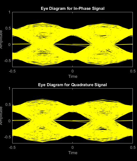
Eye Diagram of Filtered QPSK Signal
Specify the sample rate and the number of output samples per symbol parameters.
fs = 1000; sps = 4;
Create transmit filter and eye diagram objects.
txfilter = comm.RaisedCosineTransmitFilter(... 'OutputSamplesPerSymbol',sps); ed = comm.EyeDiagram('SampleRate',fs*sps,'SamplesPerSymbol',sps);
Generate random symbols and apply QPSK modulation. Then filter the modulated signal and display the eye diagram.
data = randi([0 3],1000,1); modSig = pskmod(data,4,pi/4); txSig = txfilter(modSig); ed(txSig)
More About
Measurements
Measurements assume that the eye diagram object has valid data. A valid eye diagram has two distinct eye crossing points and two distinct eye levels.
To open the measurements pane, click on the Eye Measurements button or select Tools > Measurements > Eye Measurements from the toolbar menu.
Note
For amplitude measurements, at least one bin per vertical histogram must reach 10 hits before the measurement is taken, ensuring higher accuracy.
For time measurements, at least one bin per horizontal histogram must reach 10 hits before the measurement is taken.
When an eye crossing time measurement falls within the [-0.5/Fs, 0) seconds interval, the time measurement wraps to the end of the eye diagram, i.e., the measurement wraps by 2×Ts seconds (where Ts is the symbol time). For a complex signal case, the analyze method issues a warning if the crossing time measurement of the in-phase branch wraps while that of the quadrature branch does not (or vice versa). To avoid time-wrapping or a warning, add a half-symbol duration delay to the current value in the
MeasurementDelay
property of the eye diagram object. This additional delay repositions the eye in the approximate center of the scope.
- Eye Levels - Amplitude level used to represent data bits
Eye level is the amplitude level used to represent data bits. For the displayed NRZ signal, the levels are –1 V and +1 V. The eye levels are calculated by averaging the 2-D histogram within the eye level boundaries. For example, when the EyeLevelBoundaries property is set to
[40 60]
, that is, 40% and 60% of the symbol duration, the eye levels are calculated by estimating the mean value of the vertical histogram in this window marked by the eye level boundaries.- Eye Amplitude - Distance between eye levels
Eye amplitude is the distance in V between the mean value of two eye levels.
- Eye Height - Statistical minimum distance between eye levels
Eye height is the distance between μ – 3σ of the upper eye level and μ + 3σ of the lower eye level. μ is the mean of the eye level, and σ is the standard deviation.
- Vertical Opening - Distance between BER threshold points
The vertical opening is the distance between the two points that correspond to the BERThreshold property. For example, for a BER threshold of 10–12, these points correspond to the 7σ distance from each eye level.
- Eye SNR - Signal-to-noise ratio
The eye SNR is the ratio of the eye level difference to the difference of the vertical standard deviations corresponding to each eye level:
where L1 and L0 represent the means of the upper and lower eye levels and σ1 and σ0 represent their standard deviations.
- Q Factor - Quality factor
The Q factor is the quality factor and is calculated using the same formula as the eye SNR. However, the standard deviations of the vertical histograms are replaced with those computed with the dual-Dirac analysis.
- Crossing Levels - Amplitude levels for eye crossings
The crossing levels are the amplitude levels at which the eye crossings occur.
The level at which the input signal crosses the amplitude value is specified by the DecisionBoundary property.
- Crossing Times - Times for which crossings occur
The crossing times are the times at which the crossings occur. The times are computed as the mean values of the horizontal (jitter) histograms.
- Eye Delay - Mean time between eye crossings
Eye delay is the midpoint between the two crossing times.
- Eye Width - Statistical minimum time between eye crossings
Eye width is the horizontal distance between μ + 3σ of the left crossing time and μ – 3σ of the right crossing time. μ is the mean of the jitter histogram, and σ is the standard deviation.
- Horizontal Opening - Time between BER threshold points
The horizontal opening is the distance between the two points that correspond to the BERThreshold property. For example, for a 10–12 BER, these two points correspond to the 7σ distance from each crossing time.
- Rise Time - Time to transition from low to high
Rise time is the mean time between the low and high rise/fall thresholds defined in the eye diagram. The default thresholds are 10% and 90% of the eye amplitude.
- Fall Time - Time to transition from high to low
Fall time is the mean time between the high and low rise/fall thresholds defined in the eye diagram. The default thresholds are 10% and 90% of the eye amplitude.
- Deterministic Jitter - Deterministic deviation from ideal signal timing
Jitter is the deviation of a signal’s timing event from its intended (ideal) occurrence in time [2]. Jitter can be represented with a dual-Dirac model. A dual-Dirac model assumes that the jitter has two components: deterministic jitter (DJ) and random jitter (RJ).
DJ is the distance between the two peaks of the dual-Dirac histograms. The probability density function (PDF) of DJ is composed of two delta functions.
- Random Jitter - Random deviation from ideal signal timing
RJ is the Gaussian unbounded jitter component. The random component of jitter is modeled as a zero-mean Gaussian random variable with a specified standard-deviation of σ. The RJ is computed as:
where
BER is the specified BER threshold. ρ is the amplitude of the left and right Dirac function, which is determined from the bin counts of the jitter histograms.
- Total Jitter - Deviation from ideal signal timing
Total jitter (TJ) is the sum of the deterministic and random jitter, such that TJ = DJ + RJ.
The total jitter PDF is the convolution of the DJ PDF and the RJ PDF.
- RMS Jitter - Standard deviation of jitter
RMS jitter is the standard deviation of the jitter calculated in the horizontal (jitter) histogram at the decision boundary.
- Peak-to-Peak Jitter - Distance between extreme data points of histogram
Peak-to-peak jitter is the maximum horizontal distance between the left and right nonzero values in the horizontal histogram of each crossing time.
References
[1] Stephens, Ransom. "Jitter analysis: The dual-Dirac model, RJ/DJ, and Q-scale." Agilent Technical Note (2004).
[2] Ou, N., T. Farahmand, A. Kuo, S. Tabatabaei, and A. Ivanov. “Jitter Models for the Design and Test of Gbps-Speed Serial Interconnects.” IEEE Design and Test of Computers 21, no. 4 (July 2004): 302–13. https://doi.org/10.1109/MDT.2004.34.
Extended Capabilities
C/C++ Code Generation
Generate C and C++ code using MATLAB® Coder™.
Usage notes and limitations:
Supports MEX code generation by treating the calls to the object as extrinsic. Does not support code generation for standalone applications.
See System Objects in MATLAB Code Generation (MATLAB Coder).
Version History
Introduced in R2016bR2022a: comm.EyeDiagram
has been removed
comm.EyeDiagram has been removed. To display the eye diagram of a signal, use the eyediagram
function instead.
MATLAB Command
You clicked a link that corresponds to this MATLAB command:
Run the command by entering it in the MATLAB Command Window. Web browsers do not support MATLAB commands.
Select a Web Site
Choose a web site to get translated content where available and see local events and offers. Based on your location, we recommend that you select: .
You can also select a web site from the following list
How to Get Best Site Performance
Select the China site (in Chinese or English) for best site performance. Other MathWorks country sites are not optimized for visits from your location.
Americas
- América Latina (Español)
- Canada (English)
- United States (English)
Europe
- Belgium (English)
- Denmark (English)
- Deutschland (Deutsch)
- España (Español)
- Finland (English)
- France (Français)
- Ireland (English)
- Italia (Italiano)
- Luxembourg (English)
- Netherlands (English)
- Norway (English)
- Österreich (Deutsch)
- Portugal (English)
- Sweden (English)
- Switzerland
- United Kingdom (English)
Asia Pacific
- Australia (English)
- India (English)
- New Zealand (English)
- 中国
- 日本Japanese (日本語)
- 한국Korean (한국어)