Constellation Diagram
Display and analyze input signals in IQ-plane
Libraries:
Communications Toolbox /
Comm Sinks
Communications Toolbox HDL Support /
Comm Sinks
Description
The Constellation Diagram block displays real- and complex-valued floating- and fixed-point signals in the IQ plane. Use this block to perform qualitative and quantitative analysis on modulated single-carrier signals. Specifically, the IQ-plane displays the in-phase and quadrature components of modulated signals on the real and imaginary axis of an xy-plot.
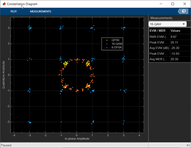
In the Constellation Diagram window, you can:
Input and plot multiple signals on a single constellation diagram. To define a reference constellation for each input signal, use the Reference Constellation parameter.
Select signals in the legend to toggle visibility of individual channels. To display the legend, use the Legend parameter on the Plot tab. For a multichannel signal, specify the input as a matrix with individual signals defined in the columns of the matrix.
Display calculated error vector magnitude (EVM) and modulation error ratio (MER) measurements for individual signals. To view and configure the measurements, select EVM/MER on the Measurements tab. When multiple signals are input, you can select which signal to use for measurements in the Channel section.
Examples
Use the Constellation Diagram block to visualize the constellation of a modulated signal.
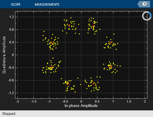
A random signal is M-PSK modulated, filtered through an AWGN channel, and passed into a Constellation Diagram to be plotted.
Run the slex_constellation_diagram model and observe the 8-PSK constellation. The received data points are shown in yellow while the red ‘+’ symbols represent the ideal constellation locations.

After running the simulation the constellation diagram shows the noisy constellation points.
You can select the Show Signal Trajectory button to display the signal trajectory of the modulated signal.
Apply QPSK modulation to a signal of random data. Pass the modulated signal through an additive white Gaussian noise (AWGN) channel. Plot the signal constellation.
The doc_qpsk_mod model generates QPSK data, applies the AWGN, and displays the resulting constellation diagram.

Run the model with the Eb/N0 of the AWGN Channel block set to 15 dB. The constellation diagram shows the QPSK symbol samples with AWGN.
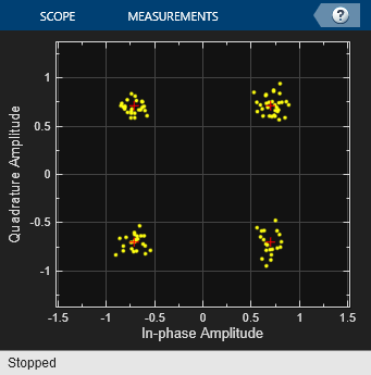
Change the Eb/N0 from 15 dB to 10 dB. The noise level increases as shown by the greater distance between the samples in the constellation diagram.

This example shows how to use the Constellation Diagram block to visualize the constellation of multi-input and multichannel modulated signals.
Pass two random 16-QAM signals through the first input port and a random 8-PSK signal through the second input port. One reference constellation can be defined for each input port. Since a single reference constellation is applied for all multichannel signals through one input port, use the Vector Concatenate (Simulink) block to concatenate multiple signals of the same data type and same reference constellation. In the case where all input signals are single channel input, then they can be directly fed in the Constellation Diagram.
Filter three signals through the AWGN channel and pass them to a Constellation Diagram.
Run Example Model to Explore Its Constellation
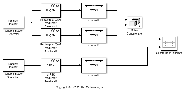
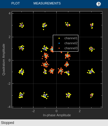
After running the simulation, the constellation diagram shows the noisy constellation points for the input signals. The received data points shown in yellow and blue represent the two 16-QAM input signals, and the received data points shown in red represent the 8-PSK signal. The red ‘+’ symbols represent the ideal constellation locations for 16-QAM modulated signals, and the white ‘+’ symbols represent the ideal constellation locations for 8-PSK modulated signal.
The trajectory trace is shown for each signal below.

Further Exploration
Use the Trace Selection pane to display measurements for the channel of interest.
Consider modifying the model to change the current modulation order.
Extended Examples
Impact of RF Effects on Communication System Performance
Model thermal noise, phase noise, and nonlinearity impairments of an RF transceiver in Simulink®.
Ports
Input
Signals, specified as separate arguments of Nsym-by-1 column vectors or Nsym-by-Nchannel matrices. Nsym is the number of symbols, and Nchannel is the number of input signal channels. Signals can have different data types and dimensions.
You must specify N input ports, where N is the Number of input ports parameter value. You can visualize up to 20 individual or collective signal channels in the constellation diagram. For example, if you create a two-channel signal for every input, then you can define up to 10 input ports.
Example: [-1 + 1i; -1 - 1i; 1 + 1i; 1 - 1i]
specifies a four-symbol input signal.
Data Types: double
Complex Number Support: Yes
Parameters
To edit block parameters interactively, use the Property Inspector. From the Simulink Toolstrip, on the Simulation tab, in the Prepare gallery, select Property Inspector.
Plot
In the Plot tab, you can adjust settings of the constellation diagram configuration, simulate the model, take a snapshot of the plot, copy the display, and print the figure. Parameters unique to the constellation diagram scope are described.
On the Plot tab, click Settings to open the Configuration Plot Settings window. This window includes parameter subsections to configure the data and axes, labels, and color and styling. Parameters unique to the constellation diagram are described on this page.
Specify the number of input ports on the scope block as an integer in the range [1, 20].
The total number of input signal channels cannot exceed 20. When you specify multichannel input signals, the total number of input signal channels limits the maximum number of input ports.
Specify the number of samples used to represent each symbol as a positive integer. The signal is downsampled by the value of this parameter before it is plotted.
Specify the number of samples to skip before plotting points as a nonnegative integer less than the Samples per symbol parameter value. This value specifies the number of samples to skip when Samples per symbol is greater than 1.
Specify the maximum number of symbols to display by
selecting Input frame length or
specifying a positive integer. To specify a positive
integer, select and then replace
<user-defined> with your
desired value. Use this parameter to limit the maximum
number of symbols that the constellation diagram displays
when you input long signals. The block plots the most
recently received symbols.
Specify the x and y-axis limits as a two-element row vector. The first element is the minimum axis value, and the second element is the maximum axis value.
If the scope window is square, then both X and Y axis will have the same limits as
AxesLimits.If the scope window is rectangular, then the smaller axis will have the same limits as
AxesLimits. The larger axes auto fills to maintain a 1:1 aspect ratio.
Tunable: Yes
Data Types: double
On the Plot tab or Measurements tab, click Reference Constellation, to open the Reference Constellation window. This window includes parameters to configure the reference constellation for each input port.
Select this parameter to show reference constellations on the plot.
Configure the reference constellation parameters for the specified input port.
Each input port has its own reference constellation. For a multichannel input signal, the block applies a single reference constellation for all signals in that input port.
Specify the reference constellation by selecting
Custom,
BPSK,
QPSK,
8-PSK,
16-QAM,
64-QAM, or
256-QAM. To specify a custom
value, first select Custom. Then
in the Custom value parameter, replace
the entry with your custom vector of symbol values.
Each input port had its own reference constellation. For a multichannel input signal, the block applies a single reference constellation for all signals in that input port.
The EVM/MER measurements use the specified reference constellation to calculate the signal quality of the modulated input signal. For more information about the signal quality measurements, see EVM and MER Measurements.
Specify the reference constellation for an input as a vector that defines symbol values for the custom modulation scheme.
Dependencies
To enable this parameter, set the Reference
constellation parameter to
Custom Reference
												Constellation
.
Specify the normalization method that the block uses for
the constellation diagram by selecting Average
power, Minimum
distance, or Peak
power.
Dependencies
To enable this parameter, set the Reference
constellation parameter to
16-QAM,
64-QAM, or
256-QAM.
Specify the average power of the reference constellation as a positive scalar. The average power is referenced to a one-ohm load. Units are in watts.
Dependencies
To enable this parameter, set the Reference
constellation parameter to
BPSK,
QPSK,
8-PSK,
16-QAM,
64-QAM, or
256-QAM.
Specify the phase offset of the reference constellation as a scalar. Units are in radians.
Dependencies
To enable this parameter, set the Reference
constellation parameter to
BPSK,
QPSK,
8-PSK,
16-QAM,
64-QAM, or
256-QAM.
The default value is
0forBPSK,16-QAM,64-QAM, and256-QAM.The default value is
pi/4for8-PSK.The default value is
pi/8forQPSK.
On the Plot tab, click Legend to toggle the display of the legend. The names listed in the legend are the names for signals connected to input ports as specified in the model. The legend does not display until the model runs with an input signal.
In the scope legend, click a signal name to toggle the signal visibility in the scope.
On the Plot tab, click Trajectory to toggle the display of the trajectory. Select this parameter to display the trajectory between constellation points for the plotted signals.
Measurements
In the Measurements tab, you can select the active channel, configure the signal quality measurements, and toggle the Measurements pane.
For more information about the signal quality measurements, see EVM and MER Measurements.
Channel
Select the active input channel for measurements from the list of input channels. Click EVM/MER to display the signal quality measurements for the active channel.
The total number of input signal channels cannot exceed 20. When you specify multichannel input signals, the total number of input signal channels limits the maximum permitted value for the Number of input ports parameter.
Measurements
Specify the duration of the EVM and MER measurement in symbols by
selecting Current Display, or
All displays or by specifying a positive
integer. To specify a positive integer, select and then replace
<user-defined> with your desired
value. The value must be a positive value in the range [1,
Symbols to display). The block computes
measurements after the number of input data samples exceeds the
measurement interval.
Specify the normalization method that the block uses for the EVM
normalization by selecting Average constellation
power or Peak constellation
power.
On the Plot tab or Measurements tab, click Reference Constellation, to open the Reference Constellation window. This window includes parameters to configure the reference constellation for each input port. For parameter descriptions, see the Reference Constellation parameter in the Plot section.
On the Measurements tab, click EVM/MER to toggle display the signal quality measurements pane. For more information, see EVM and MER Measurements.
Block Characteristics
Data Types |
|
Direct Feedthrough |
|
Multidimensional Signals |
|
Variable-Size Signals |
|
Zero-Crossing Detection |
|
More About
The Measurements pane displays the EVM and MER signal quality measurement settings and the calculation results for the specified signal channel.
EVM — An error vector is a vector in the IQ plane from the ideal constellation point to the actual point at the receiver. The EVM calculations include root mean square (RMS), peak, and average values.
You can normalize the EVMRMS and EVMAverage calculations by the average or peak constellation power method as computed using these algorithms.
EVM Normalization Method Algorithm Average constellation power EVMRMS, in percent, for average constellation power normalization:
Peak constellation power EVMRMS, in percent, for peak constellation power normalization:
The Measurements pane shows the RMS and peak EVM in percent and the average and peak EVM decibels for the selected input channel. The EVM in decibels is computed as EVM (dB) = 10 ‑ log10(EVMMS) = 20 ‑ log10(EVMRMS), where:
Ik is the in-phase value of the kth symbol in the input vector.
Qk is the quadrature phase value of the kth symbol in the input vector.
Ik and Qk represent ideal (reference) symbol values. and represent measured (received) symbol values.
N is the input vector length.
Pavg is the value for average constellation power.
Pmax is the value for peak constellation power.
The maximum EVM value in a vector is where k is the kth symbol in a vector of length N.
MER — MER is the ratio of the average power of the transmitted signal to the average power of the error vector. The Measurements pane indicates average MER measurement result in decibels for the selected signal channel.
MER is a measure of the SNR in a modulated signal, calculated in dB. The MER over N symbols is
where:
Ik is the in-phase value of the kth symbol in the input vector.
Qk is the quadrature phase value of the kth symbol in the input vector.
Ik and Qk represent ideal (reference) values. and represent measured (received) symbols.
You can programmatically configure the scope properties with callbacks or within scripts by using a scope configuration object as described in Control Scope Blocks Programmatically (Simulink).
Extended Capabilities
This block is excluded from the generated code when code generation is performed on a system containing this block.
This block can be used for simulation visibility in subsystems that generate HDL code, but is not included in the hardware implementation.
Version History
Introduced in R2013bThe Constellation Diagram block now include a unified axes limit, replacing the separate x and y axis limits. This change ensures that the system applies the specified limits to at least one axis, simplifying canvas size management. The scope automatically adjusts limits to maintain a 1:1 aspect ratio when you resize or zoom the window.
See Also
Blocks
Objects
Functions
MATLAB Command
You clicked a link that corresponds to this MATLAB command:
Run the command by entering it in the MATLAB Command Window. Web browsers do not support MATLAB commands.
选择网站
选择网站以获取翻译的可用内容,以及查看当地活动和优惠。根据您的位置,我们建议您选择:。
您也可以从以下列表中选择网站:
如何获得最佳网站性能
选择中国网站(中文或英文)以获得最佳网站性能。其他 MathWorks 国家/地区网站并未针对您所在位置的访问进行优化。
美洲
- América Latina (Español)
- Canada (English)
- United States (English)
欧洲
- Belgium (English)
- Denmark (English)
- Deutschland (Deutsch)
- España (Español)
- Finland (English)
- France (Français)
- Ireland (English)
- Italia (Italiano)
- Luxembourg (English)
- Netherlands (English)
- Norway (English)
- Österreich (Deutsch)
- Portugal (English)
- Sweden (English)
- Switzerland
- United Kingdom (English)
