DQPSK Modulator Baseband
Modulate using differential quadrature phase shift keying method
Library
PM, in Digital Baseband sublibrary of Modulation
Description
The DQPSK Modulator Baseband block modulates using the differential quadrature phase shift keying method. The output is a baseband representation of the modulated signal.
The input must be a discrete-time signal. For information about the data types each block port supports, see Supported Data Types.
Integer-Valued Signals and Binary-Valued Signals
When you set the Input type parameter to
Integer, the valid input values are 0, 1, 2, and 3. In this
case, the block accepts a scalar or column vector input signal. If the first input is
m, then the modulated symbol is
exp(jθ + jπm/2)
where θ represents the Phase rotation parameter. If a successive input is m, then the modulated symbol is the previous modulated symbol multiplied by exp(jθ + jπm/2).
When you set the Input type parameter to
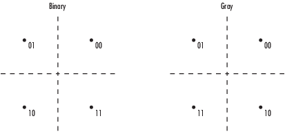
Bit, the input contains pairs of binary values. In this case,
the block accepts a column vector whose length is an even integer. The following figure
shows the complex numbers by which the block multiples the previous symbol to compute the
current symbol, depending on whether you set the Constellation ordering
parameter to Binary or Gray. The
following figure assumes that you set the Phase rotation parameter to ; in other cases, the two schematics would be rotated accordingly.

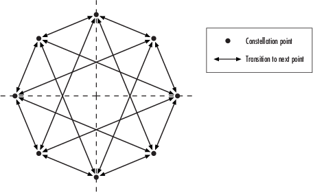
The following figure shows the signal constellation for the DQPSK modulation method when
you set the Phase rotation parameter to . The arrows indicate the four possible transitions from each symbol to the
next symbol. The Binary and Gray
options determine which transition is associated with each pair of input values.

More generally, if the Phase rotation parameter has the form for some integer k, then the signal constellation has 2k points.
Dialog Box

- Input type
Indicates whether the input consists of integers or pairs of bits.
- Constellation ordering
Determines how the block maps each pair of input bits to a corresponding integer, using either a Binary or Gray mapping scheme.
- Phase rotation (rad)
The phase difference between the previous and current modulated symbols when the input is zero.
- Output Data type
The output data type can be either
singleordouble. By default, the block sets this todouble.
Supported Data Types
| Port | Supported Data Types |
|---|---|
Input |
|
Output |
|
Pair Block
Extended Capabilities
Version History
Introduced before R2006a