QPSK Modulator Baseband
Modulate using quadrature phase shift keying method
Libraries:
Communications Toolbox /
Modulation /
Digital Baseband Modulation /
PSK
Communications Toolbox HDL Support /
Modulation /
PM
Description
The QPSK Modulator Baseband block modulates signals using the quadrature phase shift keying (QPSK) method. The output is a baseband representation of the modulated signal. This block accepts a scalar or column vector input signal. For information about the data types, see Supported Data Types.
Examples
Apply QPSK modulation to a signal of random data. Pass the modulated signal through an additive white Gaussian noise (AWGN) channel. Plot the signal constellation.
The doc_qpsk_mod model generates QPSK data, applies the AWGN, and displays the resulting constellation diagram.
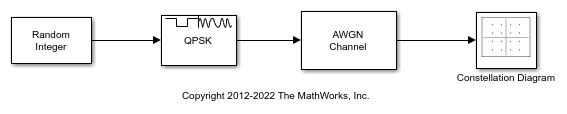
Run the model with the Eb/N0 of the AWGN Channel block set to 15 dB. The constellation diagram shows the QPSK symbol samples with AWGN.
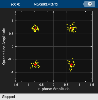
Change the Eb/N0 from 15 dB to 10 dB. The noise level increases as shown by the greater distance between the samples in the constellation diagram.

Modulate and demodulate a noisy QPSK signal.
The doc_qpsk_demod model QPSK-modulates random frames of binary data, adds noise to the modulated data, QPSK-demodulates the data, and then calculates the error rate of the received signal.
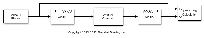
Running the simulation saves error rate results to the base workspace in the 1-by-3 row vector, ErrorVec. The first element holds the bit error rate (BER).
The AWGN Channel block has Eb/N0 set to 4.3 dB. Run the model to display the error statistics. For an Eb/N0 of 4.3 dB, the resultant BER is approximately 0.01. Your results might vary slightly.
ans =

    0.0104
Increase Eb/N0 for the AWGN to 7 dB. Rerun the simulation, and observe that the BER has decreased.
ans =

   7.0000e-04
The cm_qpsk_vs_msk model compares filtered quadrature phase shift keying (QPSK) and minimum shift keying (MSK) modulation schemes.

The model generates the filtered QPSK signal using random integer data from the Random Integer Generator block, which gets modulated by the QPSK Modulator Baseband block, and then filtered by the Raised Cosine Transmit Filter block. The model generates the MSK signal using random binary data from the Bernoulli Binary Generator block, which gets modulated by the MSK Modulator Baseband block. The model adds noise to both the filtered QPSK and MSK signals by using AWGN Channel blocks. The Eye Diagram blocks are used to visualize eye diagrams of both signals.
For filtered QPSK modulation, the values of both the in-phase and quadrature components of the signal are permitted to change at any symbol interval. For MSK modulation, the symbol interval is half that for QPSK, but the in-phase and quadrature components change values in alternate symbol epochs.
Compare eye diagram plots of a QPSK-modulated signal and an MSK-modulated signal. For QPSK, the ideal sampling period is 1/2 sample, with sampling time for both in-phase and quadrature signal components at 0.5, 1.5, 2.5, .... For MSK, the ideal sample period is 1 sample, with sampling time at 0.5, 1.5, 2.5, ... for the in-phase signal component and 1, 2, 3, ... for the quadrature signal component.


Ports
Input
Output
Parameters
Block Characteristics
More About
If you set the Input type parameter to
Integer, then valid input values are 0, 1, 2, and 3. When you
set Constellation ordering to Binary for
input m the output symbol is e(jθ + jπm/2), where θ represents the Phase offset parameter. In
this case, the block accepts a scalar or column vector signal.
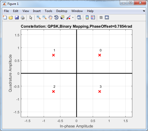
If you set the Input type parameter to
Bit, then the input contains pairs of binary values. For this
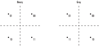
configuration, the block accepts column vectors with even lengths. When you set the
Phase offset parameter to π/4, then the block uses one of the
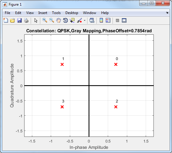
signal constellations in this figure, depending on whether you set the
Constellation ordering parameter to
Binary or Gray. In this figure, the
most significant bit is the left-most bit and is the first bit input to the block.
The Data Type Assistant helps you set data
attributes. To use the Data Type Assistant, click ![]() . For more information, see Specify Data Types Using Data Type Assistant (Simulink).
. For more information, see Specify Data Types Using Data Type Assistant (Simulink).
Algorithms
In quadrature phase shift keying, the message bits are grouped into 2-bit symbols, which are transmitted as one of four phases of a constant amplitude baseband signal. This grouping provides a bandwidth efficiency that is twice as great as the efficiency of BPSK. The general QPSK signal is expressed as
where Es is the energy per symbol, Ts is the symbol duration, and ϕ is the initial phase offset. The complex baseband representation of a QPSK signal is
In this QPSK constellation diagram, each 2-bit sequence is mapped to one of four possible states. The states correspond to phases of π/4, 3π/4, 5π/4, and 7π/4.
To improve bit error rate performance, you can map the incoming bits to a Gray-coded ordering. The primary advantage of the Gray code is that only one of the two bits changes when moving between adjacent constellation points. This table compares constellation point sequences for binary and Gray mapping.
| Binary-Coded Sequence | Gray-Coded Sequence |
|---|---|
| 00 | 00 |
| 01 | 01 |
| 10 | 11 |
| 11 | 10 |
You can apply Gray codes to higher-order modulations, as shown in this Gray-coded QPSK constellation.
The bit error probability for QPSK in AWGN with Gray coding is
which is the same as the expression for BPSK. As a result, QPSK provides the same performance with twice the bandwidth efficiency.
Extended Capabilities
Version History
Introduced before R2006a
See Also
Blocks
- QPSK Demodulator Baseband | M-PSK Modulator Baseband | BPSK Modulator Baseband | DQPSK Modulator Baseband