Error Rate Calculation
Compute bit error rate or symbol error rate of input data
Libraries:
Communications Toolbox /
Comm Sinks
Communications Toolbox HDL Support /
Comm Sinks
Description
The Error Rate Calculation block compares input data from a transmitter with input data from a receiver. The block calculates the error rate as a running statistic by dividing the total number of unequal pairs of data elements by the total number of input data elements from one source.
You can use this block to compute the symbol or bit error rate because it does not consider the magnitude of the difference between input data elements. If the inputs are bits, then the block computes the bit error rate. If the inputs are symbols, then the block computes the symbol error rate.
This figure shows the block with all ports enabled.![]()
Examples
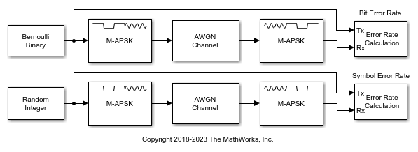
Apply 16-APSK modulation to a signal of random data. Pass the modulated signal through an AWGN channel. Demodulate the noisy 16-APSK signal. The example reports bit error rate (BER) and symbol error rate (SER) at two SNR settings.
The slex_16apsk_mod model passes a 16-APSK modulated signal through an AWGN channel, demodulates the signal and then computes the error rate statistics. The upper workflow computes the BER and the lower workflow computes the SER. Some block parameters get set by using workspace variables initialized in the PreLoadFcn callback function loads simulation variables into the workspace. For more information, see Model Callbacks (Simulink).

Run the model with the AWGN channel blocks set to EbN0 = 6 dB and display the computed BER and SER. The AWGN Channel block in the lower workflow converts the EbN0 setting to an EsN0 setting. The results are saved to the workspace variables BERVec and SERVec in 1-by-3 row vectors. The first element contains the error rate.
With EbN0 set to  6.00 dB, BER: 0.070
With EsN0 set to 12.02 dB, SER: 0.160
Change the EbN0 of the AWGN channel block to 10 dB. Run the model, display the computed BER and SER, and observe the decrease in error rate.
With EbN0 set to 10.00 dB, BER: 0.016
With EsN0 set to 16.02 dB, SER: 0.051
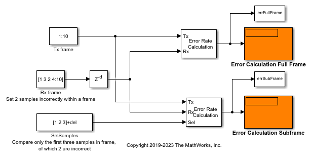
Use the Error Rate Calculation block to compute the errors for selected samples in a delayed received frame.
Explore the Model
The model includes two error calculation paths. In the top error calculation path, the Error Rate Calculation block computes errors on each full frame of data. In the bottom error calculation path, the Error Rate Calculation block computes errors on the first three samples in each frame of data and the Sel input port specifies samples from the frame to include in the error calculations. Any delay in the received samples must be accounted in the input to the Sel port.
Each
Txframe contains the integer sequence[1 2 3 4 5 6 7 8 9 10].Each
Rxframe contains the integer sequence[1 3 2 4 5 6 7 8 9 10].
The Rx frame introduces two samples errors by switching two of the samples. A Delay block adds a specified delay to the received data.

Running the Model
Run the model with the delay set to 0.
With delay = 0
            Sample error rate | # errors | # samples
Full frame:       0.200       |     20   |   100
 Sub frame:       0.667       |     20   |    30
Run the model with the delay set to 2. The delay in the received samples is included for the input to the Sel port. The full frame error calculation skips two samples due to the receive delay setting.
With delay = 2
            Sample error rate | # errors | # samples
Full frame:       0.204       |     20   |    98
 Sub frame:       0.667       |     20   |    30
Ports
Input
Transmitted data, specified as a scalar or column vector. Input signals, Tx and Rx must have same data type.
If you specify the Tx or Rx input as a scalar, the block compares this value with all elements of the other input.
If you specify Tx and Rx inputs as vectors, they must have the same size.
Data Types: single | double | int8 | int16 | int32 | uint8 | uint16 | uint32 | Boolean
Received data, specified as a scalar or column vector. Input signals, Rx and Tx must have same data type.
Data Types: single | double | int8 | int16 | int32 | uint8 | uint16 | uint32 | Boolean
Indices of the samples to consider when comparing data, specified as a positive integer or column vector of positive integers.
Dependencies
To enable this input, set the Computation
mode parameter to Select samples from
input port.
Data Types: double
Reset error count, specified as a scalar.
Dependencies
To enable this input, set the Reset port
parameter to on.
Data Types: double | Boolean
Output
Difference between transmitted and received data, returned as a column
vector of the form [R; N;
S], where:
R is the error rate.
N is the number of errors.
S is the number of samples compared.
Dependencies
To enable this port, set the Output data
parameter to Port.
Data Types: double
Parameters
To edit block parameters interactively, use the Property Inspector. From the Simulink® Toolstrip, on the Simulation tab, in the Prepare gallery, select Property Inspector.
Number of samples by which the received data lags behind the transmitted data, specified as a nonnegative integer. Use this parameter to align the samples for comparison in the transmitted and received input data vectors.
Number of data samples that the object ignores at the beginning of the comparison, specified as a nonnegative integer. Use this parameter to ignore the transient behavior of both input signals.
Samples to consider, specified as one of these values.
Entire frame— Compare all the samples of the received data to those of the transmitted frame.Select samples from mask— Set the indices of the samples to consider when making comparisons in the Selected samples from frame parameter.Select samples from port— Set the indices of the samples to consider when making comparisons in the Sel input port.
Indices of the samples to consider when comparing data, specified as a positive integer or column vector of positive integers. The default value, an empty vector, specifies that the block uses all samples from the received frame.
Dependencies
To enable this parameter, set the Computation
mode parameter to Select samples from
mask.
Output data location, specified as one of these options.
Workspace— Send the output data to the workspace variable defined by the Variable name parameter.Port— Add an output data port to the block and send the output data to that port.
Output data variable name in the MATLAB® workspace.
Dependencies
To enable this parameter, set the Output data
variable to Workspace.
Enable the Rst input port.
Option to stop the simulation after the block detects the number of errors specified in the Target number of errors parameter or performs the number of comparisons specified in the Maximum number of symbols parameter.
Option to stop the simulation after detecting this number of errors, specified as a positive integer.
Dependencies
To enable this parameter, set the Stop
simulation parameter to on.
Option to stop the simulation after comparing this number of symbols, specified as a positive integer.
Note
If you use the Simulink Coder™ rapid simulation (RSim) target to build an RSim executable, then you can tune the Target number of errors and Maximum number of symbols parameters without recompiling the model. This is useful for Monte Carlo simulations in which you run the simulation multiple times (perhaps on multiple computers) with different amounts of noise.
Dependencies
To enable this parameter, set the Stop
simulation parameter to on.
Block Characteristics
Data Types |
|
Multidimensional Signals |
|
Variable-Size Signals |
|
Extended Capabilities
When you set the Output data parameter to
Workspace, the block generates no code. Similarly, no
data is saved to the workspace if you set the Simulation mode
parameter to Accelerator or Rapid
Accelerator. If you need error rate information in these cases,
set the Output data parameter to
Port.
This block can be used for simulation visibility in subsystems that generate HDL code, but is not included in the hardware implementation.
Version History
Introduced before R2006a
MATLAB Command
You clicked a link that corresponds to this MATLAB command:
Run the command by entering it in the MATLAB Command Window. Web browsers do not support MATLAB commands.
选择网站
选择网站以获取翻译的可用内容,以及查看当地活动和优惠。根据您的位置,我们建议您选择:。
您也可以从以下列表中选择网站:
如何获得最佳网站性能
选择中国网站(中文或英文)以获得最佳网站性能。其他 MathWorks 国家/地区网站并未针对您所在位置的访问进行优化。
美洲
- América Latina (Español)
- Canada (English)
- United States (English)
欧洲
- Belgium (English)
- Denmark (English)
- Deutschland (Deutsch)
- España (Español)
- Finland (English)
- France (Français)
- Ireland (English)
- Italia (Italiano)
- Luxembourg (English)
- Netherlands (English)
- Norway (English)
- Österreich (Deutsch)
- Portugal (English)
- Sweden (English)
- Switzerland
- United Kingdom (English)