Main Content

EVM Measurement

Measure error vector magnitude (EVM)

  • EVM Measurement block

Libraries:
Communications Toolbox / Utility Blocks

Description

The EVM Measurement block measures the root mean squared (RMS) EVM, maximum EVM, and percentile EVM of a received signal. EVM is an indication of modulator or demodulator performance.

This icon shows the block with all ports enabled.EVM measurement block with all ports enabled.

Examples

expand all

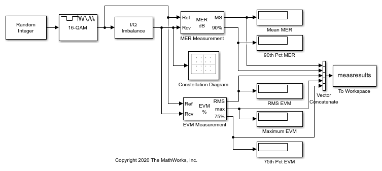
This example shows how to compute error vector magnitude (EVM) and modulation error rate (MER) measurements using Simulink® blocks.

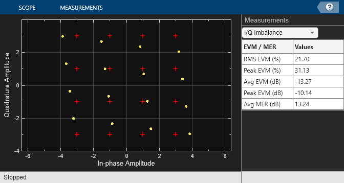
The doc_mer_and_evm model adds IQ imbalance to a 16-QAM signal. The EVM Measurement and MER Measurement blocks perform EVM and MER measurements, respectively, on the impaired signal. The Constellation Diagram block displays the impaired signal constellation and signal quality measurements. The signal quality measurements displayed in the constellation diagram window approximate the measurements reported by the EVM Measurement and MER Measurement blocks.

In this model, the I/Q Imbalance block sets the amplitude imbalance to 1 dB, the phase imbalance to 15 degrees, and the DC offset to 0. The MER Measurement block is configured to output the mean MER and the 90th percentile MER. The EVM Measurement block is configured to output the RMS EVM (normalized to the average reference signal power), the maximum EVM, and the 75th percentile EVM.

Run Model and Display Measurements

Run the model to compute the EVM and MER measurements and to display the constellation diagram.

Average MER is 16.9 dB.
90 percentile MER is 14.0 dB.
RMS EVM is 14.3%.
Maximum EVM is 20.7%.
75 percentile EVM is 17.5%.

Change the I/Q Imbalance block setting for the amplitude imbalance to 2 dB. Because the modulation accuracy decreases when the impairment value increases, the reported average MER decreases and the reported average EVM increases. Run the model again to see the degraded EVM and MER metrics.

Average MER is 13.2 dB.
90 percentile MER is 10.2 dB.
RMS EVM is 21.8%.
Maximum EVM is 31.2%.
75 percentile EVM is 26.8%.

Ports

Input

expand all

Reference signal, specified as an array of up to three dimensions. If you specify this input, the object measures the EVM of the Rcv input by using this input as a reference constellation.

The dimensions of this input must match those of the Rcv input. The object uses each element of this input as the reference symbol for the corresponding element of the Rcv input.

Dependencies

To enable this port, set the Reference signal parameter to Input port.

Data Types: single | double | fixed point
Complex Number Support: Yes

Received signal, specified as an array of up to three dimensions.

Data Types: single | double | fixed point
Complex Number Support: Yes

Output

expand all

Percentage RMS EVM over the configured measurement interval, returned as a scalar.

Data Types: double

Maximum percentage EVM over the configured measurement interval, returned as a scalar.

Dependencies

To enable this port, set the Output maximum EVM parameter to On.

Data Types: double

Value below which X% of EVM measurements fall since the last reset, returned as a scalar in the range [0, 100]. Set the value of X in the X-percentile value (%) parameter.

Dependencies

To enable this port, set the Output X-percentile EVM parameter to On.

Data Types: double

Number of symbols used to measure the X-percentile EVM, returned as a positive integer.

Dependencies

To enable this port, set the Output X-percentile EVM and Output the number of symbols processed parameters to On.

Data Types: double

Parameters

expand all

To edit block parameters interactively, use the Property Inspector. From the Simulink® Toolstrip, on the Simulation tab, in the Prepare gallery, select Property Inspector.

Normalization method used in EVM calculation, specified as Average reference signal power, Average constellation power, or Peak constellation power. For more information, see Algorithms.

Average constellation power in watts, specified as a positive scalar.

Dependencies

To enable this parameter, set the Normalize RMS error vector parameter to Average constellation power.

Peak constellation power in watts, specified as a positive scalar.

Dependencies

To enable this parameter, set the Normalize RMS error vector parameter to Peak constellation power.

Reference signal source. To provide an explicit reference signal against which to measure received signal, set this parameter to Input port. To measure the EVM of the received signal against a reference constellation, set this parameter to Estimated from reference constellation.

Reference constellation points, specified as a vector of complex or real values.

Dependencies

To enable this parameter, set the Reference signal parameter to Estimated from reference constellation.

Measurement interval source for RMS and maximum EVM measurements, specified as one of these values.

  • Input length — Measure the EVM using only the current samples.

  • Entire history — Measure the EVM for all samples.

  • Custom — Measure the EVM over an interval you specify and use a sliding window.

  • Custom with periodic reset — Measure the EVM over an interval you specify and reset the block after measuring over each interval.

Custom measurement interval in samples, specified as a positive integer.

Dependencies

To enable this parameter, set the Measurement interval parameter to Custom or Custom with periodic reset.

Dimensions over which the block averages the EVM measurements, specified as an integer or row vector of integers in the range [1, 3]. For example, to average across the rows, set this parameter to 2.

This block supports variable-size inputs of the dimensions across which the averaging takes place. However, the input size for the non-averaged dimensions must remain constant. For example, if the input has size [1000 3 2] and you set this parameter to [1 3], then the output size is [1 3 1] and the number of elements in the second dimension must remain fixed at 3.

Option to add the max port to output maximum EVM measurements.

Option to add the X% port to output X-percentile EVM measurements. When you set this parameter to On, X-percentile EVM measurements persist until you reset the block. The block performs these measurements by using all of the input frames since the last reset. You can set the value of X in the X-percentile value (%) parameter.

Value below which X% of EVM measurements fall, specified as a scalar in the range [0, 100].

Dependencies

To enable this parameter, set the Output X-percentile EVM parameter to On.

Option to add the nSym port to output number of symbols used to measure the X-percentile EVM.

Dependencies

To enable this parameter, set the Output X-percentile EVM parameter to On.

Type of simulation to run, specified as Interpreted execution or Code generation.

  • Interpreted execution — Simulate the model by using the MATLAB® interpreter. This option requires less startup time, but the speed of subsequent simulations is slower than with the Code generation option. In this mode, you can debug the source code of the block.

  • Code generation — Simulate the model by using generated C code. The first time you run a simulation, Simulink generates C code for the block. The model reuses the C code for subsequent simulations unless the model changes. This option requires additional startup time, but the speed of the subsequent simulations is faster than with the Interpreted execution option.

For more information, see Interpreted Execution vs. Code Generation (Simulink).

Block Characteristics

Data Types

double | fixed point | integer | single

Multidimensional Signals

yes

Variable-Size Signals

yes

Algorithms

The implementation supports three normalization methods. You can normalize measurements according to the average power of the reference signal, average constellation power, or peak constellation power. Different industry standards follow one of these normalization methods.

The algorithm calculates the RMS EVM value differently for each normalization method.

EVM Normalization MethodAlgorithm
Reference signal

EVMRMS=1Nk=1N(ek)1Nk=1N(Ik2+Qk2)×100

Average power

EVMRMS(%)=1001Nk=1N(ek)Pavg

Peak power

EVMRMS(%)=1001Nk=1N(ek)Pmax

In these equations:

  • ek = ek=(IkI˜k)2+(QkQ˜k)2

  • Ik is the in-phase measurement of the kth symbol in the burst.

  • Qk is the quadrature phase measurement of the kth symbol in the burst.

  • N is the input vector length.

  • Pavg is the average constellation power.

  • Pmax is the peak constellation power.

  • Ik and Qk represent ideal (reference) values. I˜k and Q˜k represent measured (received) symbols.

The maximum EVM is the maximum EVM value in a frame or EVMmax=maxk[1,...,N]{EVMk}, where k is the kth symbol in a burst of length N.

The definition for EVMk depends on which normalization method you select for computing measurements. The implementation supports these algorithms.

EVM Normalization MethodAlgorithm
Reference signal

EVMk=ek1Nk=1N(Ik2+Qk2)×100

Average power

EVMk=100ekPavg

Peak power

EVMk=100ekPmax

The implementation computes the X-percentile EVM by creating a histogram of the incoming EVMk values. This output provides the EVM value below which X% of the EVM values fall.

References

[1] IEEE® Standard 802.16-2017. "Part 16: Air Interface for Broadband Wireless Access Systems." March 2018.

[2] 3GPP TS 45.005 V8.1.0 (2008–05). "Radio Access Network: Radio transmission and reception".

[3] IEEE Standard 802.11a™-1999. "Part 11: Wireless LAN Medium Access Control (MAC) and Physical Layer (PHY) specifications: High-speed Physical Layer in the 5 GHz Band." 1999.

Extended Capabilities

Version History

Introduced in R2009b