Digital Predistortion to Compensate for Power Amplifier Nonlinearities
This example shows how to use digital predistortion (DPD) in a transmitter to offset the effects of nonlinearities in a power amplifier. This example use power amplifier models that were obtained from Power Amplifier Characterization example to simulate two cases. In the first simulation, the RF transmitter sends two tones. In the second simulation, the RF transmitter sends a 5G-like OFDM waveform with 100 MHz bandwidth.
DPD with Two Sinusoidal Test Signals
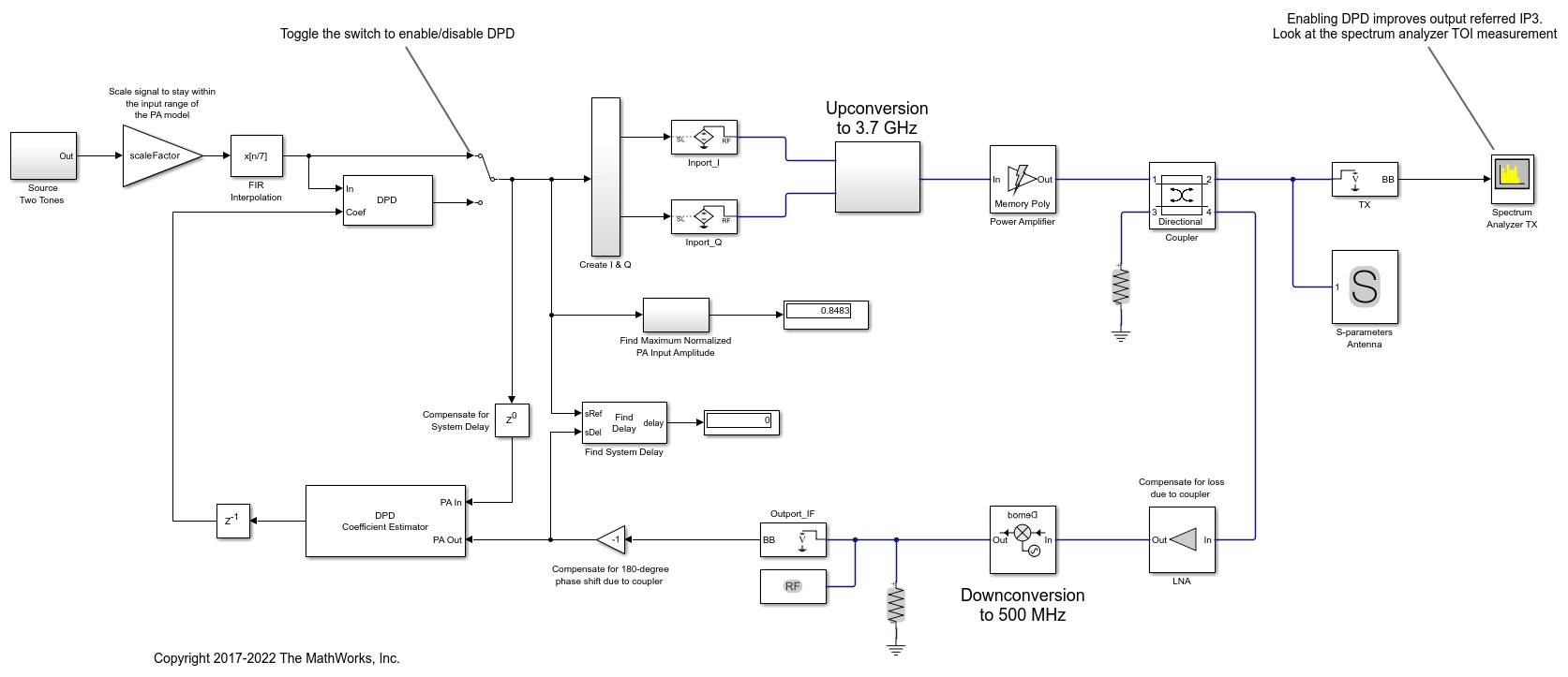
The simrfV2_powamp_dpd.slx model simulates a system-level PA + DPD with two tones.
The model includes a two-tone signal generator that is used for testing the output-referred third-order intercept point of the system. The model includes upconversion to RF frequency using an I-Q modulator, the PA model, a coupler to sniff the output of the PA, and an S-parameter block representing the antenna loading effect. The receiver chain performs downconversion to low intermediate frequency. Notice that the simulation bandwidth of this system is 107.52 MHz.
The model can be simulated without DPD when the toggle switch is in the up position.
model = 'simrfV2_powamp_dpd';
open_system(model)
sim(model)
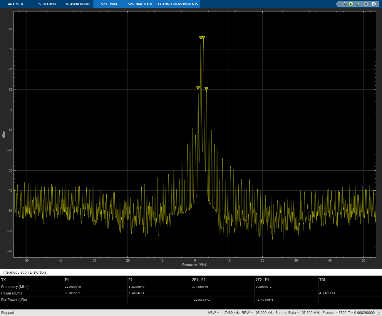
The manual switch is toggled to enable the DPD algorithm. When toggled, the TOI (third-order intercept point) is improved significantly. Inspect the distortion measurement in the Spectrum Analyzer to validate these results and see how the power of the harmonics is reduced thanks to the DPD linearization.
Before the two-tone signal enters the DPD block or the power amplifier, it goes through an FIR interpolator, the same FIR interpolator used during PA characterization. This is necessary because the power amplifier model was obtained for the sample rate after interpolation, not the original sample rate of the two-tone signal, and oversampling the signal is required for modeling high order nonlinearities introduced by the power amplifier.
The desired amplitude gain of the DPD Coefficient Estimator is set based on the expected gain of the power amplifier (obtained during PA characterization), because in addition to linearization, the overall goal is to make the combined gain from the DPD input to the power amplifier output as close to the expected gain as possible. To estimate the DPD coefficients correctly, the input signals to the DPD Coefficient Estimator block, PA In and PA Out, must be aligned in the time domain. This is verified by the Find Delay block which shows that the delay introduced by the RF system is 0. Moreover, PA In and PA Out must be accurate baseband representations of the power amplifier input signal and output signal, i.e. no extra gain or phase shift. Otherwise, the DPD Coefficient Estimator block would not observe the power amplifier correctly and would not produce the right DPD coefficients. This is done by ensuring that both the upconversion and downconversion steps have a gain of 1 and the loss and phase shift due to the coupler are properly compensated for before the feedback signal reaches PA Out.
The purpose of the scale factor in front of the FIR interpolator is to help utilize the linearized power amplifier effectively. Even with DPD enabled, two undesirable scenarios may occur. The two-tone signal may be very small with respect to the input range of the linearized system, hence under-utilizing the amplification capability of the linearized system. Or the two-tone signal may be so large that the power amplifier model operates outside the range observed during PA characterization and therefore the power amplifier model may not be an accurate model of the physical device. We use the following heuristic approach to set the scale factor.
Assuming that the DPD block perfectly linearizes the power amplifier to achieve the expected amplitude gain, then the maximum input amplitude allowed by the DPD block should be the maximum power amplifier output amplitude observed during PA characterization divided by the expected amplitude gain. The scale factor before the DPD block should then be the maximum input amplitude allowed by the DPD block divided by the maximum amplitude of the interpolated signal observed during PA characterization.
The system model has a block that calculates the maximum normalized PA input amplitude. If it is equal to 1, it means that the baseband signal entering the RF system has a maximum amplitude equal to the maximum PA input amplitude observed during PA characterization. Therefore, if the maximum normalized PA input amplitude is smaller than 1, the scale factor set by the heuristic approach above may be increased. If the maximum normalized PA input amplitude is greater than 1, the scale factor should be reduced.
set_param([model '/Manual Switch'],'action','1')
sim(model)
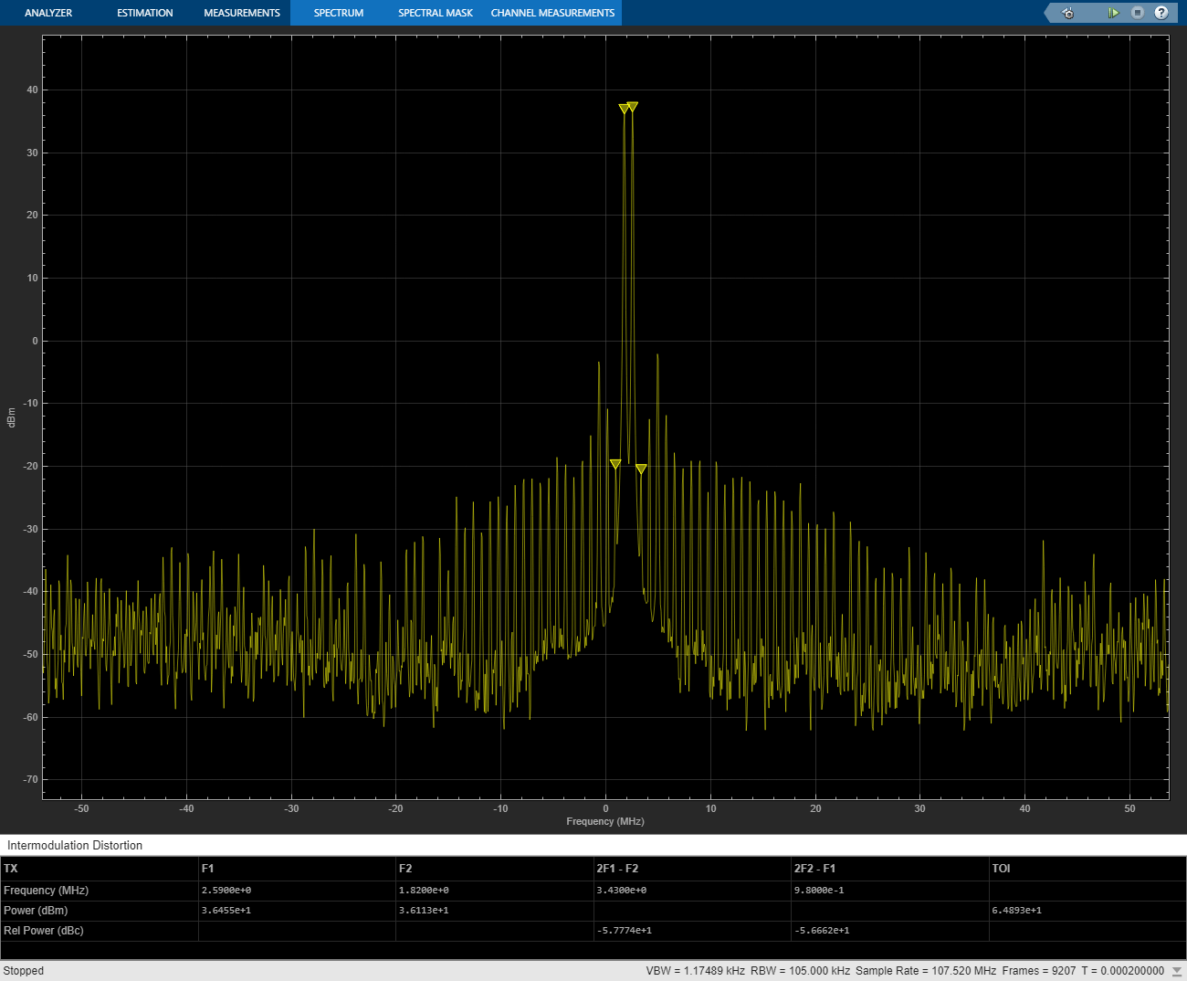
By changing the degree and the memory depth defined in the DPD Coefficient Estimator block, you can find the most suitable tradeoff between performance and implementation cost.
close_system(model,0)
close all; clear
DPD with a 5G-like OFDM Waveform
The simrfV2_powamp_dpd_comms.slx model simulates a system-level model PA + DPD with a 5G-like OFDM waveform.
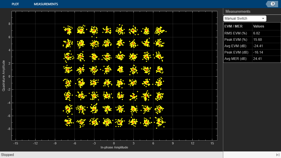
The structure of this Simulink model is the same as that of the previous Simulink model. The signal being amplified is now a 5G-like OFDM waveform, rather than a two-tone signal. Oversampling is done at the OFDM modulator within the baseband signal generation block. The spectrum analyzer measures ACPR instead of TOI and we add a subsystem to measure the EVM and MER of the amplified OFDM waveform.
Without DPD linearization, the system achieves an average Modulation Error Ratio of 24.4 dB, as seen from the constellation plot measurement.
model = 'simrfV2_powamp_dpd_comms';
open_system(model)
sim(model)
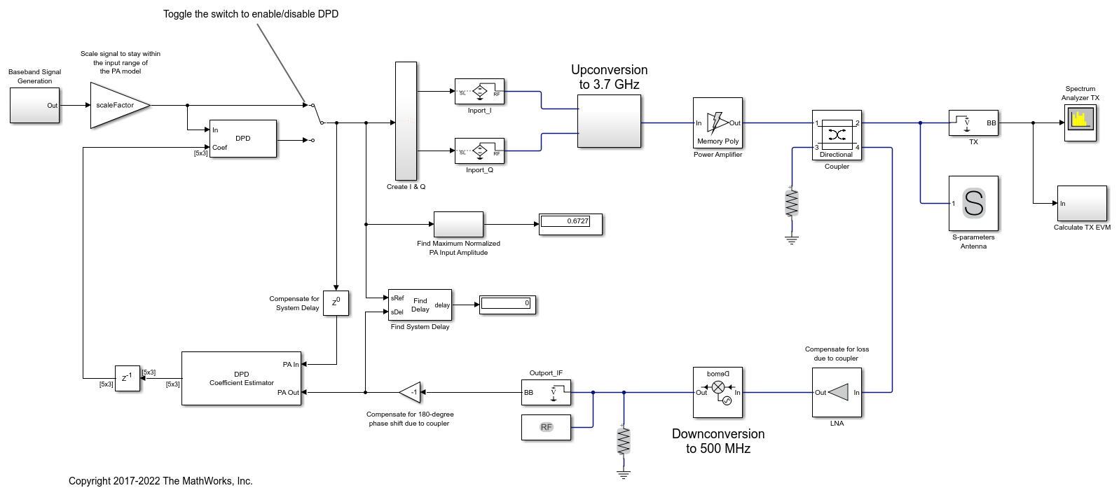
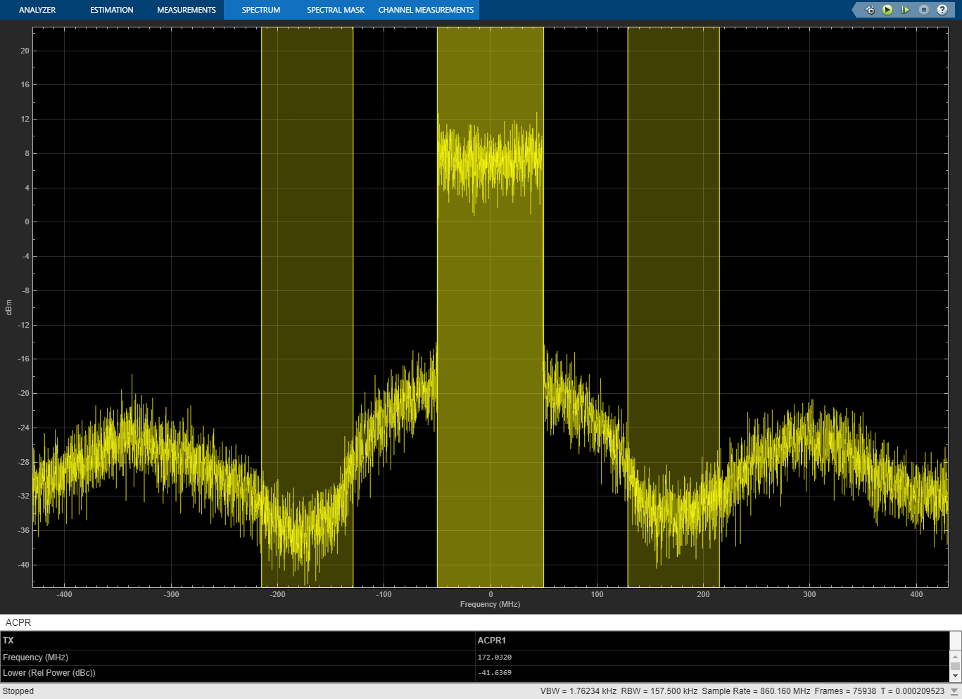
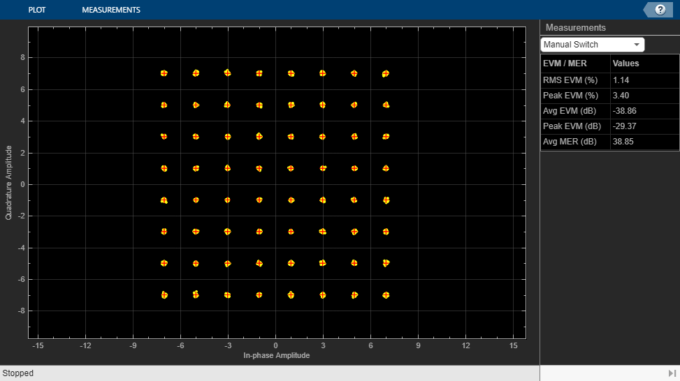
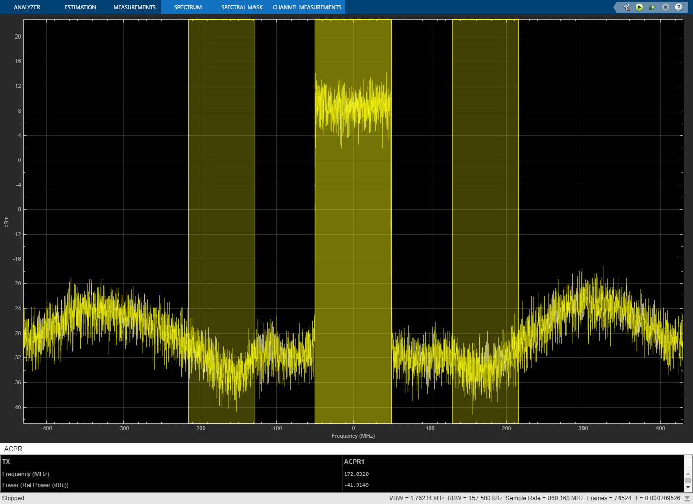
The manual switch is toggled to enable the DPD algorithm. When toggled, the average MER is improved significantly.
set_param([model '/Manual Switch'],'action','1')
sim(model)
Selected Bibliography
Morgan, Dennis R., Zhengxiang Ma, Jaehyeong Kim, Michael G. Zierdt, and John Pastalan. "A Generalized Memory Polynomial Model for Digital Predistortion of Power Amplifiers." IEEE® Transactions on Signal Processing. Vol. 54, No. 10, October 2006, pp. 3852–3860.
Gan, Li, and Emad Abd-Elrady. "Digital Predistortion of Memory Polynomial Systems Using Direct and Indirect Learning Architectures." In Proceedings of the Eleventh IASTED International Conference on Signal and Image Processing (SIP) (F. Cruz-Roldán and N. B. Smith, eds.), No. 654-802. Calgary, AB: ACTA Press, 2009.