Impact of Thermal Noise on Communication System Performance
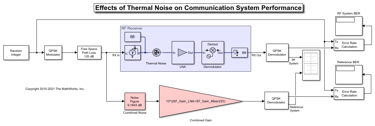
This example shows how to use the RF Blockset™ Circuit Envelope library to model thermal noise in a super-heterodyne RF receiver and measure its effects on a communications system noise figure (NF) and bit error rate (BER). A Communications Toolbox™ reference model with parameters computed using Friis equations and a RF Blockset Noise Testbench are used to verify the results.
RF Receiver System Architecture
The Modulator and Channel subsystems consist of Communications Toolbox blocks that model:
A QPSK-modulated waveform of random bits
A raised cosine pulse-shaping filter for spectral limiting
free-space path loss
The RF receiver subsystem, shown in light purple, consists of RF Blockset blocks:
An Inport block converts the complex input waveform to available power in the RF system with reference impedance equal to the Source impedance and assigns the input modulation waveform to a
2.1GHz RF carrier.A noise source to set the RF system noise floor for all simulation carrier frequencies. The block performs this action when White is selected for the mask Noise distribution option. To set the Noise power spectral density level, a value of
4*K*T*50is used (Kis Boltzmann's constant,Tis set to a room temperature of290kelvin, and50ohms is the system reference impedance).Cascaded RF amplifier and RF demodulator blocks with specified noise figure and gain. These blocks only enable noise impairments. The Demodulator block's image reject filter is enabled using a mask checkbox and defines with other mask parameters a bandpass filter whose edges are
2.0and2.2GHz. This filter prevents the down-conversion of thermal noise centered around 2.6 GHz or folding of other carrier frequencies with noise into the intermediate frequency (IF) defined as the absolute difference of the RF and LO frequencies. If the image rejection filter is removed, the noise contribution on the IF increases above the estimation provided by Friis equations and the BER will deteriorate.An Outport block, with the parameter Sensor type is set to
Power, Carrier frequencies set to the IF frequency, and Output parameter is set toComplexbaseband. These block settings enable the RF system to supply a complex baseband communication signal to the ensuing Communication Toolbox system blocks.A Configuration block to set model conditions for simulation. Since the model's RF Blockset section has only included noise impairments, an accurate simulation can be achieved by setting the Configuration block Fundamental tones to the Inport Carrier (RF),
5e8Hz and Demodulator Local oscillator (LO),1.6e9Hz frequencies and the Harmonic order1. Use the Configuration blocks View button to explore simulation carrier frequencies.All blocks in the RF receiver are matched to 50 ohms. To understand the effects of impedance mismatch on noise simulation see,
RF Noise Modeling (RF Blockset).
The reference system, shown in red, consists of:
A Communications Toolbox Receiver Thermal Noise block that includes both the thermal noise floor along with the amplifier and demodulator block noise. The Friis Equation is used to correctly combined noise contributed by the amplifier and demodulator blocks. You can find the calculation in the model's pre-load callback function.
A Simulink Gain block that models the combined gain of the RF receiver.
Baseband filters and demodulators process the received signal.
Circuit Envelope Simulation of RF Receiver

Select Simulation > Run.
Error Rate Calculation blocks compute the BER for the system and reference. To observe the BER as it approaches steady state, increase the total simulation time. For this example, the steady-state bit error rate is approximately 1e-4.
Computing RF Receiver Noise Figure and Gain
To model noise and gain in the RF Blockset circuit envelope environment:
In the Configuration block dialog, select Simulate noise.
Specify the Noise figure (dB) parameter of RF Amplifier and RF Mixer blocks in your system. The following specifications for the RF receiver in this example produce a combined noise figure of
9.16dB (as per the Friis Equation): LNA gain of20dB, LNA noise figure of9dB, Demodulator gain of-5dB and RF Demodulator noise figure of15dB.


RF Blockset Noise Figure Testbench
The RF Blockset Noise Figure Testbench simplifies the measurement of system noise figure. To setup a noise figure test system, insert an RF Noise Figure Testbench in a new model. Copy the settings found in the Model Properties Callbacks PreLoadFcn to the new models Model Properties Callback InitFcn.
For the system composed of RF Blockset blocks in the above model, copy the LNA and Demodulator blocks with previously set parameters to the new model. The Testbench includes a Noise source that sets the noise floor.
Connect the Stimulus terminal of the testbench to the In terminal of the LNA and the Out terminal of the Demodulator to testbench Response terminal. A Display block can be connected to the testbench NF terminal to display the measured Noise figure.
Set the Testbench mask parameters. The RF Input frequency (Hz) is
2.1GHz and the IF Output frequency (Hz) is.5GHz as in the previous example. A10e6Hz Baseband bandwidth (Hz) was chosen for this example. The mask instructions provide additional information for configuring the testbench.
For the Communications Friis system in the above model, copy the Combined Noise and Gain blocks with previously set parameters to the new model. The Combined Noise block's Add 290K antenna noise checkbox needs to be deselected since the Testbench includes a Noise source that sets the noise floor.
Three RF Blockset blocks are included: an Outport, an Inport and a Configuration since the testbench expects RF Blockset blocks at its connection points. The type setting for the Inport and Outport blocks is Power. Since the Communication branch is agnostic to carrier frequencies, these blocks Carrier frequencies and Fundamental tones need to be the same and are set to
2.1GHz. The Output parameter of the Outport isComplex Baseband. For accuracy, the configuration block Step size needs an Envelope bandwidth ( Step size of1/80e6s) at least 8 times larger than the 10 MHz Baseband bandwidth of the testbench.
Run Noise Figure Testbench

Select Simulation > Run.
Exploring Example
You can include additional RF model impairments using RF block mask selections: Impedance mismatch, nonlinearities or LO isolation.