OFDM Resource Grid and Channel Estimation
Introduction
In real-world channels, delay spread and multipath are common and the wireless channel can distort the transmitted signal, making it harder to recover the original data. To address this, the receiver first performs channel estimation. This means using known pilot signals to measure how the channel affects different subcarriers.
To understand channel estimation you need to understand OFDM resource grid, pilot symbols, pilot locations and clusters
OFDM Resource Grid
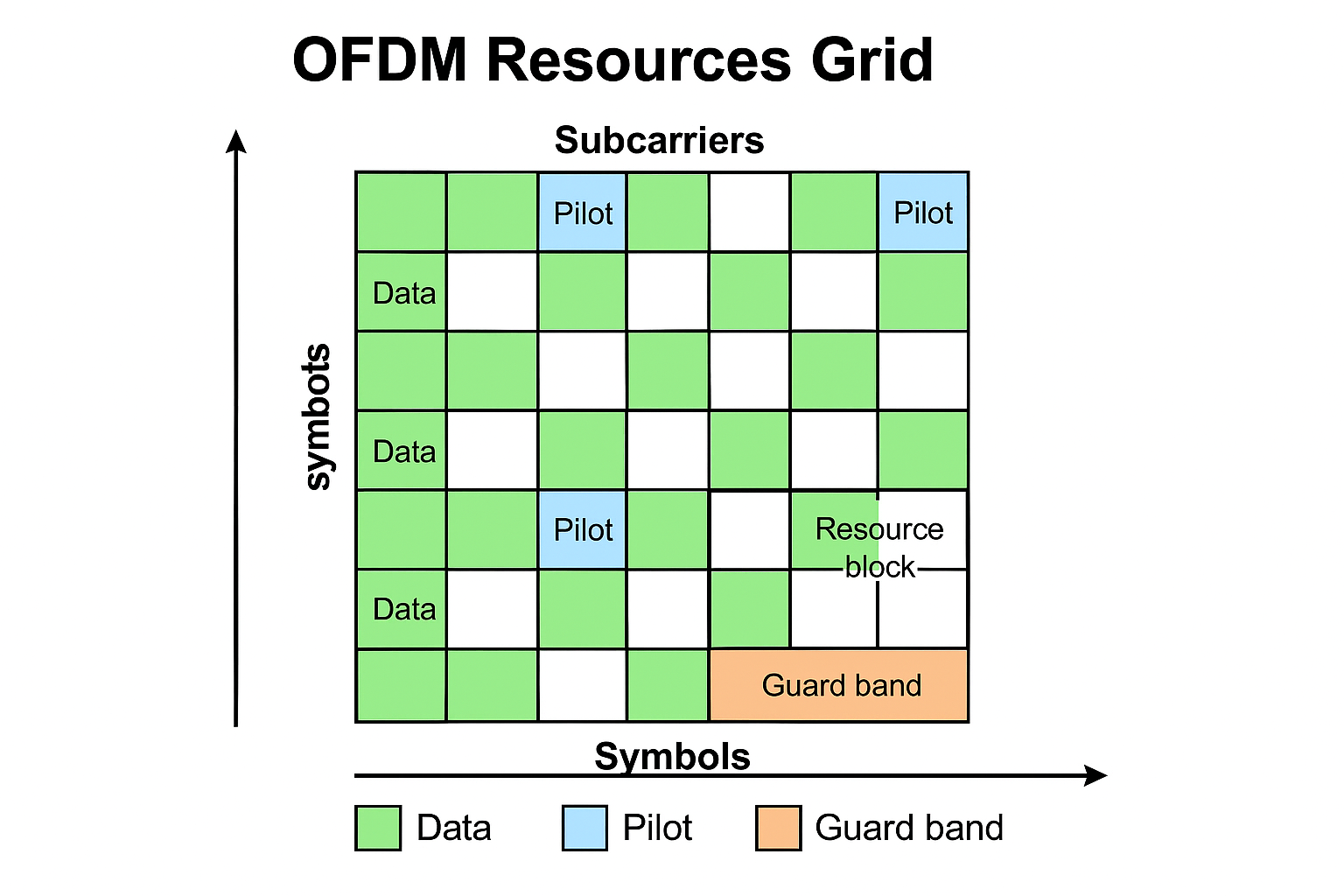
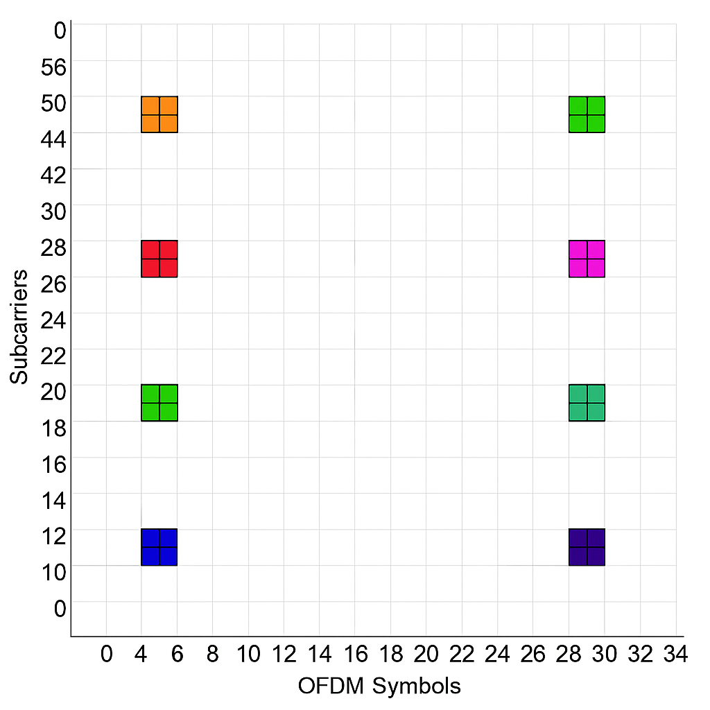
This diagram shows an OFDM resource grid:
X-axis (Symbols): Represents OFDM symbols in the time domain.
Y-axis (Subcarriers): Represents subcarriers in the frequency domain.
Green: Data symbols used for transmitting user information.
Blue: Pilot symbols used for channel estimation and synchronization.
Orange: Guard band to prevent interference between adjacent channels.
Resource Block or Cluster: A group of adjacent subcarriers and OFDM symbols, forming a basic unit for resource allocation.
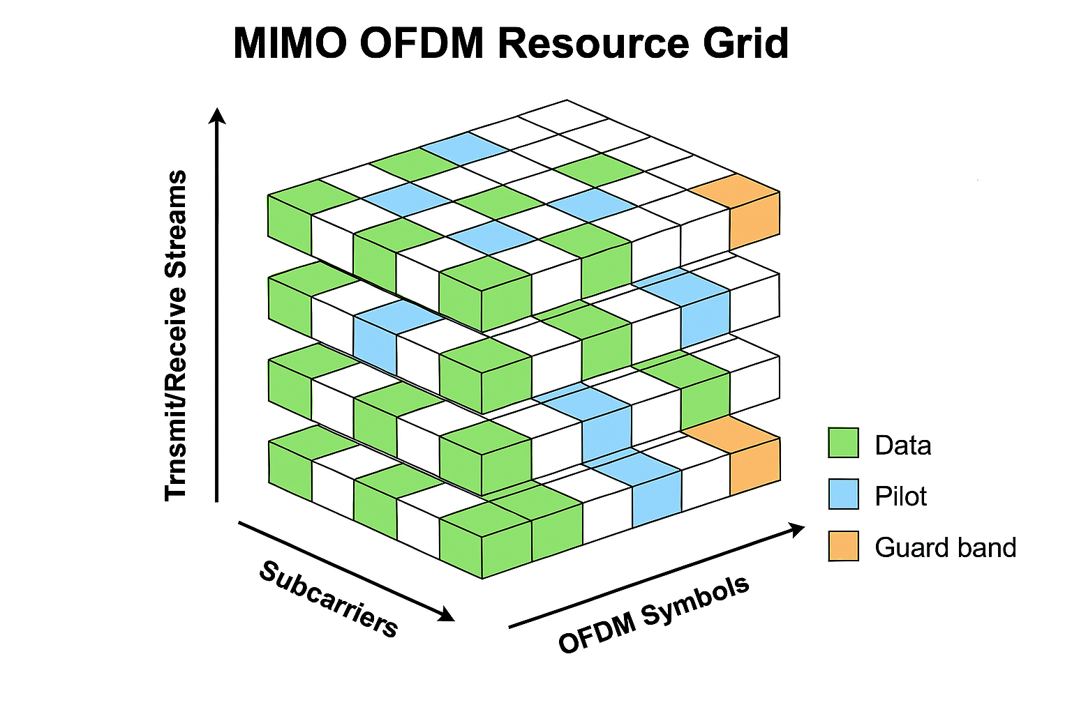
For MIMO OFDM systems the grid is 3-D to include the transmit streams or receive streams.
Pilot symbols are known reference signals inserted into the OFDM resource grid. Both the transmitter and receiver know these symbols, which enables the receiver to estimate the channel by comparing received pilot signals to the transmitted ones.
Pilot locations specify where in the grid the pilot symbols are placed. Each location is defined by a subcarrier index (frequency) and an OFDM symbol index (time). The pilot configuration object, such as ofdmPilotConfig, manages these locations and ensures that pilots are distributed according to system requirements. The configuration supports flexible placement, allowing pilots to be grouped in clusters that match the channel’s coherence properties.
Clusters are groups of nearby pilot locations where the channel is assumed to remain constant. Clusters do not need to be rectangular or contiguous; any pattern is valid as long as the channel does not vary significantly within the cluster. The pilot configuration object can define clusters of any shape, and each cluster contains enough pilot symbols to estimate the channel for the associated transmit antennas.
The number and placement of clusters are design choices. For example in 5G, a resource block (RB), the smallest allocatable unit consists of 12 subcarriers × 1 slot. A slot typically contains 14 OFDM symbols (for normal cyclic prefix), and multiple slots form a subframe. Bandwidth Parts (BWPs) are logical partitions of the carrier bandwidth to support flexible numerology.
Increasing the number of clusters improves channel estimation accuracy but reduces the available data rate, since pilots occupy resource elements that do not carry user data. The arrangement of clusters also affects the complexity of interpolation and extrapolation needed to estimate the channel at non-pilot location.
Channel Estimation
In wireless communication, the channel acts like a time-varying filter altering signals due to reflections, obstacles and motion. It changes and distorts the transmitted signal as it travels from the transmitter to the receiver. Channel estimation is the process of determining how the wireless channel affects signals from each transmit stream to each receive antenna in that OFDM system. By estimating the channel, the receiver can undo these distortions and recover the original data more accurately. Without accurate estimation, equalization and recovery fail, leading to poor performance. In a MIMO (Multiple-Input, Multiple-Output) OFDM (Orthogonal Frequency Division Multiplexing) system, multiple antennas transmit simultaneously, their signals overlap at the receiver, making it challenging to separate and identify the effect of channel on each transmitted stream.
To address this, pilot symbols are inserted at specific locations in the OFDM time-frequency grid. Both the transmitter and receiver know the values and positions of these pilot symbols. At the receiver, the channel response is estimated at these pilot locations by comparing the received pilot symbols to their known transmitted values.
However, pilots are only present at selected points in the grid. To estimate the channel at all other locations (where data is transmitted), the receiver uses interpolation (and sometimes extrapolation) based on the pilot estimates. This process fills in the channel response across the entire grid, enabling accurate equalization and data recovery.
Roles of Cyclic Prefix
A cyclic prefix (CP) is a fundamental feature in OFDM systems. It is a copy of the last part of each OFDM symbol, inserted at the beginning of the symbol before transmission. The cyclic prefix acts as a guard interval, absorbing the effects of multipath delay spread in wireless channels. This ensures that delayed copies of the signal do not interfere with the next symbol.
For each OFDM symbol, a segment from the end of the symbol (of length equal to the CP) is copied and prepended to the symbol.
The receiver discards the CP before demodulation, using only the main part of the symbol for FFT processing.
The length of the CP is chosen based on the expected maximum delay spread of the channel; it must be at least as long as the channel’s impulse response to be fully effective.
This technique is also used when transmitting pilot signals to the receiver for channel estimation.
The Four-Dimensional Channel Response
In MIMO OFDM systems, the wireless channel is described by a four-dimensional structure: Subcarrier × OFDM Symbol × Transmit Stream × Receive Antenna.
Each OFDM frame is organized along subcarriers (frequency) and OFDM symbols (time).
For every subcarrier-symbol pair, the channel is represented by a matrix, not a single value. This matrix captures how signals from each transmit stream arrive at each receive antenna.
Stacking these matrices across all subcarriers and symbols forms a four-dimensional array. This 4-D view allows the receiver to estimate and equalize the channel independently for every subcarrier and symbol.
Importance of Orthogonal Pilots
In MIMO OFDM systems, orthogonality means that the pilot symbols sent from different transmit streams are designed so that they do not interfere with each other at the receiver. Mathematically, two signals are orthogonal if their inner product is zero meaning the signals are completely independent.
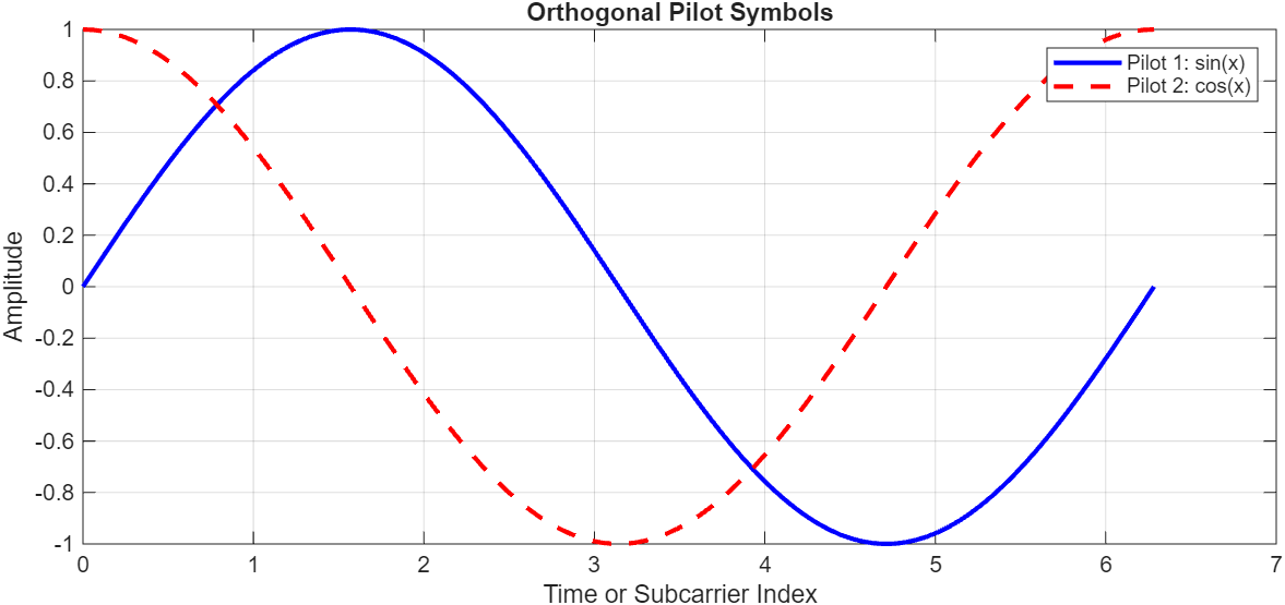
Where the blue and red curves cross, their product is zero. Over the full interval, the area under the product of the two curves is zero and this is orthogonality.
In MIMO, each transmit stream sends its own signal. At the receiver, all these signals arrive mixed together. The receiver needs to figure out how each transmit stream's signal traveled through the channel to each receive antenna. If the pilots from different antennas are not orthogonal, their effects get mixed up, and the receiver cannot separate them cleanly. In MIMO OFDM, when pilot signals are orthogonal, the receiver can use simple linear algebra to separate the mixed signals and estimate the channel for each transmit-receive pair independently.
Pilot symbols for each transmit stream are chosen so that, across a cluster of pilot locations, the set of pilot vectors forms an orthogonal matrix or full rank matrix.
For example, consider a 4-by-4 orthogonal pilot matrix suitable for 4 transmit antennas and 4 pilot locations in a cluster. This is called a Hadamard matrix.
In the above matrix, take any two different rows, multiply corresponding elements,
and sum the results. The total will always be zero. For example, row 1 and row 2:
(1×1)+(1×−1)+(1×1)+(1×−1)=1−1+1−1=0.
Example 1 — Demonstrate importance of local consistency, orthogonality, and pilot placement
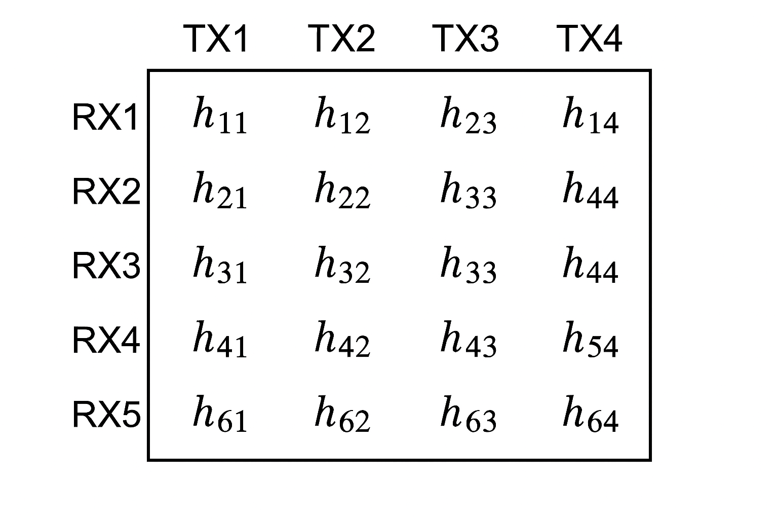
To understand better, consider an OFDM system with 4 transmit antennas and 6 receive antennas. The channel between each transmit stream and each receive antenna is represented by a complex gain or a complex number describing amplitude and phase shift. For every transmit-receive pair, there is a unique channel coefficient.
So, the channel matrix H has:
Rows — 6 (one for each receive antenna)
Column — 4 (one for each transmit stream)
Total elements in H is 6 -by-4 which is 24.
Each element is a complex number or there are 24 complex unknowns which is the effect of the channel from each transmit antenna to each receive antenna. To understand the channel effect on the entire transmission you need to estimate the 24 unknowns.
You now have only 6 equations from the receive antennas and is not sufficient to solve for 24 unknown elements in the H matrix.
To solve for these 24 unknowns, you need to make two key assumptions:
Channel Constancy in a Neighborhood — Assume the channel H does not change within a small region of the subcarrier-symbol grid for example, a 2-by-2 block of subcarriers and symbols. This means you can treat H as constant over N nearby locations (N ≥ 4).
Orthogonal Pilot Signals — At these N locations, transmit N known TX vectors that are orthogonal or linearly independent. For 4 TX antennas, you need at least 4 such locations, each with a different orthogonal TX vector.
To estimate H,
Collect N measurements (N ≥ 4), each with a different orthogonal pilot vector.
Stack the received vectors into a 6-by-N matrix B.
Stack the known pilot vectors into a 4-by-N matrix A.
Solve the linear system, B = H⋅A.
Now, you have enough information to estimate all 24 elements of H within that cluster where you made your assumptions.
To make MIMO OFDM channel estimation both solvable and practical, you must design your pilots to be orthogonal and well-placed, and you must exploit the fact that the channel doesn’t change too quickly within small regions. Only by combining these two strategies can you reliably estimate the channel and enable robust communication.
Example 2 — Subsets of Antennas and Flexible Clustering
Now consider 8 transmit antennas. Instead of using all antennas at every pilot location, you can activate only a subset of antennas at a time. Multiple subsets of antennas can send their reference signals (pilots) at the same subcarrier-symbol locations. At each such location, you only estimate the columns of the channel matrix H corresponding to the antennas that are active.
To achieve this split the 8 transmit stream into 2 groups:
Group 1: antennas [1, 2, 5, 6]
Group 2: antennas [3, 4, 7, 8]
At certain subcarrier-symbol locations, only Group 1 is active; at others, only Group 2 is active. At each location, you design the pilots signals that are orthogonal. For each group, you need at least as many orthogonal pilot vectors as the number of active antennas in that group (N = number of active antennas).
This helps to achieve efficiency because all antennas are not active at every pilot location, which can reduce pilot overhead and allow more flexible pilot placement. This approach is used in advanced systems like 5G, where pilot patterns (such as DMRS) are carefully designed for large antenna arrays.
Thinking in terms of clusters allows you to design pilot patterns that are not limited to simple, contiguous blocks. You can have arbitrary shapes and arrangements, as long as the pilots within each cluster are orthogonal and the channel is roughly constant within the cluster. This mental framework is powerful because it works for any number of antennas, any pilot pattern, and any grouping of antennas. It’s the foundation for modern, scalable MIMO OFDM channel estimation.