UFMC vs. OFDM Modulation
This example compares Universal Filtered Multi-Carrier (UFMC) with Orthogonal Frequency Division Multiplexing (OFDM) and highlights the merits of the candidate modulation scheme for Fifth Generation (5G) communication systems.
UFMC was considered as an alternate waveform to OFDM in the 3GPP RAN study phase I during 3GPP Release 14.
Introduction
OFDM, as a multi-carrier modulation technique, has been widely adopted by 4G communication systems, such as LTE and Wi-Fi®. It has many advantages: robustness to channel delays, single-tap frequency domain equalization, and efficient implementation. What is often not highlighted are its costs such as the loss in spectral efficiency due to higher side-lobes and the strict synchronization requirements. New modulation techniques are, thus, being considered for 5G communication systems to overcome some of these factors.
As an example, an LTE system at 20 MHz channel bandwidth uses 100 resource blocks of 12 subcarriers each, at an individual subcarrier spacing of 15 kHz. This utilizes only 18 MHz of the allocated spectrum, leading to a 10 percent loss. Additionally, the cyclic prefix of 144 or 160 samples per OFDM symbol leads to another ~7 percent efficiency loss, for an overall 17 percent loss in possible spectral efficiency.
With the now defined ITU requirements for 5G systems, applications require higher data rates, lower latency and more efficient spectrum usage. This example focuses on the new modulation technique known as Universal Filtered Multi-Carrier (UFMC) and compares it with OFDM within a generic framework.
s = rng(211); % Set RNG state for repeatabilitySystem Parameters
Define system parameters for the example. These parameters can be modified to explore their impact on the system.
numFFT = 512;        % number of FFT points
subbandSize = 20;    % must be > 1
numSubbands = 10;    % numSubbands*subbandSize <= numFFT
subbandOffset = 156; % numFFT/2-subbandSize*numSubbands/2 for band center

% Dolph-Chebyshev window design parameters
filterLen = 43;      % similar to cyclic prefix length
slobeAtten = 40;     % side-lobe attenuation, dB

bitsPerSubCarrier = 4;   % 2: 4QAM, 4: 16QAM, 6: 64QAM, 8: 256QAM
snrdB = 15;              % SNR in dB
Universal Filtered Multi-Carrier Modulation
UFMC is seen as a generalization of Filtered OFDM and FBMC (Filter Bank Multi-carrier) modulations. The entire band is filtered in filtered OFDM and individual subcarriers are filtered in FBMC, while groups of subcarriers (sub-bands) are filtered in UFMC.
This subcarrier grouping allows one to reduce the filter length (when compared with FBMC). Also, UFMC can still use QAM as it retains the complex orthogonality (when compared with FBMC), which works with existing MIMO schemes.
The full band of subcarriers (N) is divided into sub-bands. Each subband has a fixed number of subcarriers and not all sub-bands need to be employed for a given transmission. An N-pt IFFT for each subband is computed, inserting zeros for the unallocated carriers. Each subband is filtered by a filter of length L, and the responses from the different sub-bands are summed. The filtering is done to reduce the out-of-band spectral emissions. Different filters per subband can be applied, however, in this example, the same filter is used for each subband. A Chebyshev window with parameterized side-lobe attenuation is employed to filter the IFFT output per subband [ 1 ].
The transmit-end processing is shown in the following diagram.

% Design window with specified attenuation
prototypeFilter = chebwin(filterLen, slobeAtten);

% Transmit-end processing
%  Initialize arrays
inpData = zeros(bitsPerSubCarrier*subbandSize, numSubbands);
txSig = complex(zeros(numFFT+filterLen-1, 1));

hFig = figure;
axis([-0.5 0.5 -100 20]);
hold on;
grid on

xlabel('Normalized frequency');
ylabel('PSD (dBW/Hz)')
title(['UFMC, ' num2str(numSubbands) ' Subbands, '  ...
    num2str(subbandSize) ' Subcarriers each'])

%  Loop over each subband
for bandIdx = 1:numSubbands

    bitsIn = randi([0 1], bitsPerSubCarrier*subbandSize, 1);
    % QAM Symbol mapper
    symbolsIn = qammod(bitsIn, 2^bitsPerSubCarrier,InputType='bit', ...
    UnitAveragePower=true);
    inpData(:,bandIdx) = bitsIn; % log bits for comparison

    % Pack subband data into an OFDM symbol
    offset = subbandOffset+(bandIdx-1)*subbandSize;
    symbolsInOFDM = [zeros(offset,1); symbolsIn; ...
                     zeros(numFFT-offset-subbandSize, 1)];
    ifftOut = ifft(ifftshift(symbolsInOFDM));

    % Filter for each subband is shifted in frequency
    bandFilter = prototypeFilter.*exp( 1i*2*pi*(0:filterLen-1)'/numFFT* ...
                 ((bandIdx-1/2)*subbandSize+0.5+subbandOffset+numFFT/2) );
    filterOut = conv(bandFilter,ifftOut);

    % Plot power spectral density (PSD) per subband
    [psd,f] = periodogram(filterOut, rectwin(length(filterOut)), ...
                          numFFT*2, 1, 'centered');
    plot(f,10*log10(psd));

    % Sum the filtered subband responses to form the aggregate transmit
    % signal
    txSig = txSig + filterOut;
end
set(hFig,Position=figposition([20 50 25 30]));
hold off;

% Compute peak-to-average-power ratio (PAPR)
pm = powermeter(Measurement="Peak-to-average power ratio",ComputeCCDF=true);
paprUFMC = pm(txSig);
disp(['Peak-to-Average-Power-Ratio (PAPR) for UFMC = ' num2str(paprUFMC) ' dB']);
Peak-to-Average-Power-Ratio (PAPR) for UFMC = 8.2379 dB
OFDM Modulation with Corresponding Parameters
For comparison, we review the existing OFDM modulation technique, using the full occupied band, however, without a cyclic prefix.
symbolsIn = qammod(inpData(:), 2^bitsPerSubCarrier,InputType='bit', ...
    UnitAveragePower=true);

% Process all sub-bands together
offset = subbandOffset;
symbolsInOFDM = [zeros(offset, 1); symbolsIn; ...
                 zeros(numFFT-offset-subbandSize*numSubbands, 1)];
ifftOut = sqrt(numFFT).*ifft(ifftshift(symbolsInOFDM));

% Plot power spectral density (PSD) over all subcarriers
[psd,f] = periodogram(ifftOut, rectwin(length(ifftOut)), numFFT*2, ...
                      1, 'centered');
hFig1 = figure;
plot(f,10*log10(psd));
grid on
axis([-0.5 0.5 -100 20]);
xlabel('Normalized frequency');
ylabel('PSD (dBW/Hz)')
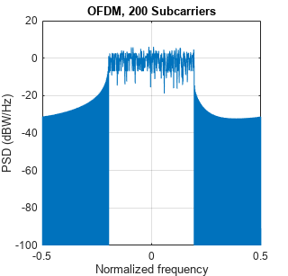
title(['OFDM, ' num2str(numSubbands*subbandSize) ' Subcarriers'])
set(hFig1, 'Position', figposition([46 50 25 30]));

% Compute peak-to-average-power ratio (PAPR)
pm = powermeter(Measurement="Peak-to-average power ratio",ComputeCCDF=true);
paprOFDM = pm(ifftOut);
disp(['Peak-to-Average-Power-Ratio (PAPR) for OFDM = ' num2str(paprOFDM) ' dB']);
Peak-to-Average-Power-Ratio (PAPR) for OFDM = 8.8843 dB
Comparing the plots of the spectral densities for OFDM and UFMC schemes, UFMC has lower side-lobes. This allows a higher utilization of the allocated spectrum, leading to increased spectral efficiency. UFMC also shows a slightly better PAPR.
UFMC Receiver with No Channel
The example next highlights the basic UFMC receive processing, which, like OFDM, is FFT-based. The subband filtering extends the receive time window to the next power-of-two length for the FFT operation. Every alternate frequency value corresponds to a subcarrier main lobe. In typical scenarios, per-subcarrier equalization is used for equalizing the joint effect of the channel and the subband filtering.
In this example, only the subband filter is equalized because no channel effects are modeled. Noise is added to the received signal to achieve the desired SNR.
% Add WGN
rxSig = awgn(txSig, snrdB, 'measured');
The receive-end processing is shown in the following diagram.

% Pad receive vector to twice the FFT Length (note use of txSig as input)
%   No windowing or additional filtering adopted
yRxPadded = [rxSig; zeros(2*numFFT-numel(txSig),1)];

% Perform FFT and downsample by 2
RxSymbols2x = fftshift(fft(yRxPadded));
RxSymbols = RxSymbols2x(1:2:end);

% Select data subcarriers
dataRxSymbols = RxSymbols(subbandOffset+(1:numSubbands*subbandSize));

% Plot received symbols constellation
constDiagRx = comm.ConstellationDiagram(ShowReferenceConstellation=false, ...
    Position=figposition([20 15 25 30]), ...
    Title='UFMC Pre-Equalization Symbols', ...
    Name='UFMC Reception', ...
    AxesLimits=[-150 150]);
constDiagRx(dataRxSymbols);

% Use zero-forcing equalizer after OFDM demodulation
rxf = [prototypeFilter.*exp(1i*2*pi*0.5*(0:filterLen-1)'/numFFT); ...
       zeros(numFFT-filterLen,1)];
prototypeFilterFreq = fftshift(fft(rxf));
prototypeFilterInv = 1./prototypeFilterFreq(numFFT/2-subbandSize/2+(1:subbandSize));

% Equalize per subband - undo the filter distortion
dataRxSymbolsMat = reshape(dataRxSymbols,subbandSize,numSubbands);
EqualizedRxSymbolsMat = bsxfun(@times,dataRxSymbolsMat,prototypeFilterInv);
EqualizedRxSymbols = EqualizedRxSymbolsMat(:);

% Plot equalized symbols constellation
constDiagEq = comm.ConstellationDiagram(ShowReferenceConstellation=false, ...
    Position=figposition([46 15 25 30]), ...
    Title='UFMC Equalized Symbols', ...
   Name='UFMC Equalization');
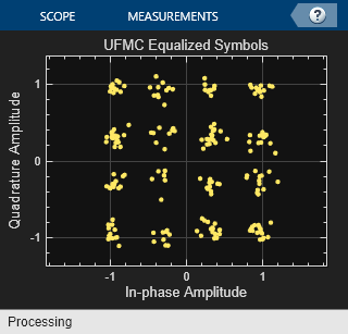
constDiagEq(EqualizedRxSymbols);

% BER computation
BER = comm.ErrorRate;

% Perform hard decision and measure errors
rxBits = qamdemod(EqualizedRxSymbols, 2^bitsPerSubCarrier,OutputType='bit', ...
    UnitAveragePower=true);
ber = BER(inpData(:), rxBits);

disp(['UFMC Reception, BER = ' num2str(ber(1)) ' at SNR = ' ...
    num2str(snrdB) ' dB']);
UFMC Reception, BER = 0 at SNR = 15 dB
% Restore RNG state
rng(s);
Conclusion and Further Exploration
The example presents the basic characteristics of the UFMC modulation scheme at both transmit and receive ends of a communication system. Explore different system parameter values for the number of sub-bands, number of subcarriers per subband, filter length, side-lobe attenuation, and SNR.
Refer to FBMC vs. OFDM Modulation for an example that describes the Filter Bank Multi-Carrier (FBMC) modulation scheme. The F-OFDM vs. OFDM Modulation example describes the Filtered-OFDM modulation scheme.
UFMC is considered advantageous in comparison to OFDM by offering higher spectral efficiency. Subband filtering has the benefit of reducing the guards between sub-bands and also reducing the filter length, which makes this scheme attractive for short bursts. The latter property also makes it attractive in comparison to FBMC, which suffers from much longer filter length.
Selected Bibliography
Schaich, F., Wild, T., Chen, Y., "Waveform Contenders for 5G - Suitability for Short Packet and Low Latency Transmissions", Vehicular Technology Conference, pp. 1-5, 2014.
Wild, T., Schaich, F., Chen Y., "5G air interface design based on Universal Filtered (UF-)OFDM ", Proc. of 19th International Conf. on Digital Signal Processing, pp. 699-704, 2014.