Analog Input
Acquire data from multiple analog channels of data acquisition device
Libraries:
Data Acquisition Toolbox
Description
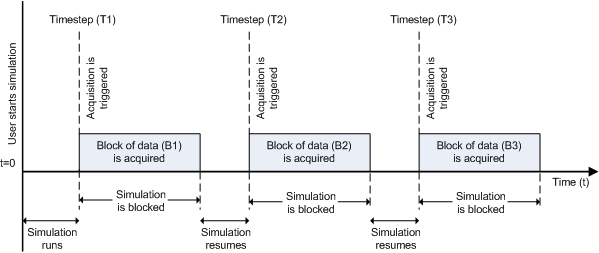
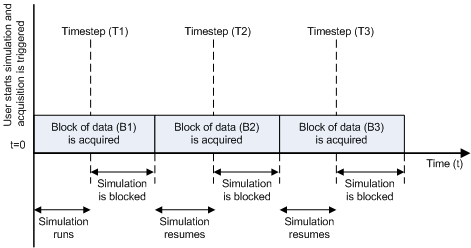
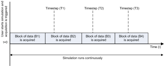
The Analog Input block opens, initializes, configures, and controls an analog data acquisition device. The opening, initialization, and configuration of the device occur once at the start of the model execution. During the model run time, the block acquires data either synchronously (deliver the current block of data the device is providing) or asynchronously (stream buffered incoming data).
The block has no input ports. It has one or more output ports, depending on the configuration you choose in its dialog box.
Use the Analog Input block to incorporate live measured data into Simulink® for:
System characterization
Algorithm verification
System and algorithm modeling
Model and design validation
Controller design
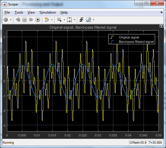
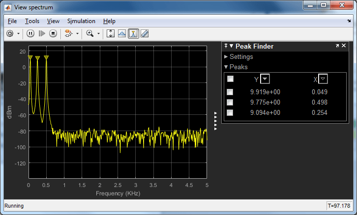
The following diagram shows the basic analog input usage configuration, with which you can:
Read acquired data at each time step or once per model execution.
Analyze the data, or use it as input to a system in the model.
Optionally display results.

Notes
To use this block, you need both Data Acquisition Toolbox™ and Simulink software.
Some devices are not supported by the Simulink blocks in Data Acquisition Toolbox. To see if your device supports Simulink, refer to Supported Hardware.
You can use the Analog Input block only with devices that support clocked acquisition. To acquire data using devices that do not support clocking, use the Analog Input (Single Sample) block.
Other Supported Features
If you have DSP System Toolbox™, you can use this block for signal applications.
This block supports the use of text accelerator mode, but not Rapid Accelerator or code generation.
The block supports the use of model referencing, so that your model can include other Simulink models as modular components.
For more information on these features, see the Simulink documentation.
Examples
Ports
Output
Parameters
Version History
Introduced in R2016b

